Optimization of Diffuser Design for Axial Flow Blood Pump
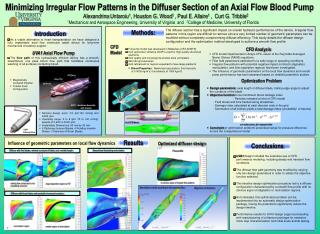
Study on minimizing irregular flow patterns in diffuser section of blood pump to enhance hydraulic efficiency. Utilized CFD analysis to optimize diffuser geometry and achieve smooth flow profile for improved pump performance.

Optimization of Diffuser Design for Axial Flow Blood Pump
E N D
Presentation Transcript
Minimizing Irregular Flow Patterns in the Diffuser Section of an Axial Flow Blood Pump AlexandrinaUntaroiu1, Houston G. Wood1 , Paul E. Allaire1 , Curt G. Tribble2 1Mechanical and Aerospace Engineering, University of Virginia and 2College of Medicine, University of Florida Methods: The diffuser section has a significant impact on overall hydraulic performance of the device. Irregular flow patterns in this region are difficult to remove since a very limited number of geometric parameters can be modified without completely compromising diffuser efficiency. This study details the diffuser design configuration and the optimization method developed to achieve a smooth flow profile. Introduction As a viable alternative to heart transplantation we have designed a fully implantable axial flow ventricular assist devicefor long-term mechanical circulatory support. UVA1 Axial Flow Pump The flow path of this hydraulically efficient device has a smooth, streamlined, one pass blood flow path that facilitates continuous washing of all surfaces contacting blood. CFD Analysis CFDModel Full pump model was developed in BladeGen (CFX-ANSYS). Grid generation software GridPro used for high quality structured elements. Grid quality and convergence studies were completed. 800,000 grid elements. Grid refinement for regions expected to have large gradients • CFD model implemented in Ansys-CFX, solver of the Reynolds-Averaged Navier Stokes (RANS) equations. • Flow field parameters estimated for a wide range of operating conditions. • Irregular flow patterns with potential negative impact on blood (stagnation, recirculation, and flow separation regions) have been investigated. • The influence of geometric parameters on the local flow dynamics and overall pump performance has been assessed based on detailed parametric studies. • Blood Properties: Newtonian assumption; fluid viscosity of 0.0035 kg/m*s; fluid density of 1050 kg/m3. Diffuser • Magnetically Levitated Impeller • Tubular Axial Configuration Impeller Optimization Problem Inducer • Design parameters: axial length of diffuser blade, trailing edge angle to adjust the curvature of the blade • Objective function to be minimized: blood damage index - Particles released at inlet of CFD model - Fluid stress and time tracked along streaklines - Damage index calculated at each discrete node in the grid - Summation of all indices yields a total damage index (‘probability’ of trauma) • Constraintof optimization problem: prescribed range for pressure difference across the computational model UVA1 - Sectioned Assembly with Impeller • Nominal design point: 4.5 lpm,100 mmHg and 6,500 rpm. • Operating range: 2 to 8 lpm, 70 to 140 mmHg, speeds of 5,000 to 8,000 rpm. • Implantable Dimensions: 90 mm by 35 mm • 6 Stationary Inducer Blades, 4 Rotating Impeller Blades, 3 Stationary Diffuser Blades. Full CFD Model = scalar stress, t = exposure time UVA1 External View Results Influence of geometric parameters on local flow dynamics Optimized diffuser design Conclusions Diffuser with five blades, minimal curvature of blade, and variable length Streamlines illustrating recirculation Flow profile UVA1 design included the extensive use of CFD performance modeling, including steady and transient flow conditions. The diffuser flow path geometry was modified by varying only two design parameters in order to satisfy the objective function selected. This iterative design optimization procedure led to a diffuser configuration characterized by a smooth flow profile with no obvious signs of stagnation or recirculation regions. As formulated, this optimization problem can be implemented into an automatic design optimization package, having the potential to significantly reduce the design timeline. Performance results for UVA1 design support proceeding with manufacturing of a titanium prototype for extensive mock loop characterization and initial acute animal testing. no obvious signs of irregular flow patterns rotating flow component is not completely removed large stagnation regions at TE Streamlines colored according to the exposure time Magnitude of Velocities Diffuser with three blades and gradually increased curvature recirculation region smaller region of recirculation