Download
1 / 24
240 likes | 428 Vues
Progress on Comparison to X-band Klystron-based CLIC Option. D. Schulte for the CLIC team Special thanks to A. Grudiev , B. Jeanneret , Ph. Lebrun, G. McMonagle , I. Syratchev CLIC-ACE February 3 rd , 2010. Rational. Two concerns exist

E N D
Progress on Comparison to X-band Klystron-based CLIC Option D. Schulte for the CLIC team Special thanks to A. Grudiev, B. Jeanneret, Ph. Lebrun, G. McMonagle, I. Syratchev CLIC-ACE February 3rd, 2010
Rational • Two concerns exist • A klystron-based machine can more easily demonstrate the basic RF unit • A klystron-based machine may be cheaper at lower energies • Want to address these issues with no prejudice • Focus on 500GeV machine since this is the point where concerns are most relevant CLIC-ACE February 3rd, 2011
Use current CLIC 500GeV design and simply replace the drive beam with klystrons • Minimal changes • May not be the optimum klystron based design • Optimise the CLIC 500GeV design for klystron, using heavily damped structures and remaining compatible with up-grade • We limit ourselfs to structures which have been developed in the process of the CLIC 500GeV optimisation • Full optimisation of CLIC for klystrons • Not done • Significant amount of work • Obviously profit from JLC-X/NLC work Strategy CLIC-ACE February 3rd, 2011
Luminosity Comparison to NLC Lower beam current per luminosity is due to smaller vertical emittance in CLIC Smaller horizontal emittance in CLIC allows to run at smaller bunch charges beamstrahlung fixes optimum N/σx CLIC-ACE February 3rd, 2011
RF Comparison to NLC CLIC-ACE February 3rd, 2011
Replacing Drive Beam with Klystrons CLIC-ACE February 3rd, 2011
2x Anticipated =0.6 for klystron 30 meters X3.16 =0.92 54 MW / structure 250 MeV/unit CLIC-ACE February 3rd, 2011
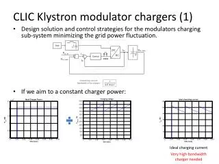
75 MW Klystron (approx 2000 per LINAC) • Solenoid focussing (25kW per klystron) • 55% efficiency • 0.0002 duty cycle (120 Hz, 1.6µs) • Average RF output power of klystron 14.4kW • 1 kW heater power per klystron • Line type modulator • Pulse transformer 20% wasted power with rise and fall time • Thyratron switch, 600 W per thyratron • Overall Power Requirement per Klystron/Modulator • 55.3 kW • 246 MW/two linac (2264 klystrons) • This technology is known and works NLC Initial Baseline Design CLIC-ACE February 3rd, 2011
75 MW Klystron (approx 2000 per LINAC) • ppm periodic permanent magnet focussing (no solenoids) • 55% efficiency • 0.0002 duty cycle (120 Hz, 1.6µs) • Average RF output power of klystron 14.4kW • 1 kW heater power per klystron • Solid State Modulator (1 per two klystrons) • Pulse transformer 20% wasted power with rise and fall time • Overall Power Requirement per Klystron/Modulator(0.5) • 37.5 kW (would at 50Hz be 16.2kW) • 167 MW/two linacs • Klystron development was not finished, some problems with pulse width and high rep rate, peak power achieved • Modulators • Many iterations were done on different types of solid state switches, but still with pulse transformer. Only recently can we confidently say that this technology is properly developed • This will be our baseline, even if work is needed to fully demonstrate it NLC Baseline Design circa 2002 CLIC-ACE February 3rd, 2011
Pulse Compression Efficiency 240 480 CLIC-ACE February 3rd, 2011
Efficiency • Consider drive beam based machine up to roughly twice as efficient • But more work to be done at 500GeV drive beam based CLIC • some inconsistencies between Igor and Bernard • Need to include other systems in comparison • e.g. magnets of drive beam complex Klystron Drive beam *strongly depends on rise and fall time CLIC-ACE February 3rd, 2011
We use • No parameter adjustment for • Integer number of structures per klystron pair • Integer compression factor • To be done done once we fix a design • But will not change the conclusions very much • Will adjust other parameters a bit, e.g. klystron power, RF pulse length • 7200 klystrons for CLIC 500 baseline Klystron Number CLIC-ACE February 3rd, 2011
Drive beam CLIC 500 • Average total RF input power 24.3MW • Wall plug 53.5MW (Igor), 89MW (Bernard) • Klystrons-based CLIC 500 • Average total RF input power 24.3MW • 112 MW wall plug (7200 klystrons) • NLC • Average total RF input power 47.3MW • Wall plug 167MW (4464 klystrons) Wall Plug Power Note: 10% overhead included CLIC-ACE February 3rd, 2011
Semi-optimised Structure CLIC-ACE February 3rd, 2011
Structure has been optimised for luminosity per unit power • Figure of merit: Lbx/ N ηRF->beam • Larger emittances than at 3TeV have been assumed • Upgrade potential has been included by requiring • Structure length be 23 or 48 cm • i.e. a 500 GeV structure replaces 1 or 2 3TeV-structures • RF pulse length be 240 or 480 ns • 240ns for 23cm long structures • i.e. for 48cm long structures the drive beam decelerator can be 2 times longer • Input power per structure is similar to 3TeV • Did not quite make it but came close Reminder: 500 GeV Structure Choice CLIC-ACE February 3rd, 2011
Luminosity at 500GeV Short range wake limits bunch charge Calculate: Bunch charge N(G,a,f) Luminosity L0.99(G,a,f) Limit on long-range wake at second bunch • Depends on assumptions on • emittances • beta-functions
Figure of Merit CLIC-ACE February 3rd, 2011
Klystron-based machine has some cost reduction • No drive beam generation complex • No drive beam turn-arounds • No decelerators • But some cost increase • Second tunnel is needed for klystron, modulators and pulse compressors • Klystrons, modulators, pulse compressors etc. • Do not yet have a cost comparison of klystron-based vs. drive beam based machine • More work needed • But we have an estimate of the relative linac cost for the klystron-based machine • Allows to identify the best klystron-based machine Cost Calculation CLIC-ACE February 3rd, 2011
Cost versus Gradient CLIC-ACE February 3rd, 2011
Linac Cost versus Luminosity per Power 5 2 3 CLIC drive beam baseline Interesting structures NLC is at FoM 1.7/2.15 for Εy=40/25nm CLIC-ACE February 3rd, 2011
Structure Parameters CLIC-ACE February 3rd, 2011
Structure Parameters CLIC-ACE February 3rd, 2011
Documenting the current status • Report is being prepared • Some inconsistencies need to be fixed • E.g. power efficiency • Establish some cost model for 500GeV • Also needed for drive beam based machine • Based on CLIC cost evaluation • Further work once we have a scenario for CLIC energy staging • Emittances at 500GeV have strong impact on structure choice • Upgrade will place many constraints Future CLIC-ACE February 3rd, 2011
Using current CLIC 500 design with klystrons requires 7200 klystrons • Prediction for wall plug to RF efficiency could indicate that drive beam is twice more efficient • But needs careful detailed evaluation on drive beam side • RF to beam efficiency is about 33% larger than for NLC structure due to heavy damping • Reducing the gradient to reduce the klystron number leads to about 5000 klystrons • But cost cannot be reduced strongly (<20% for main linac) • The cost for the different options does not seem to vary very strongly • Error of the model is still large • Comparison of cost klystron vs. drive beam remains to be done Conclusion CLIC-ACE February 3rd, 2011