Download
1 / 38
380 likes | 527 Vues
RIDGE LOADED X-BAND CRAB CAVITY FOR CLIC. Vasim Khan 30.01.2013. CLIC crab cavity – base line design. Racetrack cell shape. Courtesy of G. Burt, et. al. Ridge loaded waveguide structures: Rama Calaga. http:// indico.cern.ch/conferenceDisplay.py?confId=178008.

E N D
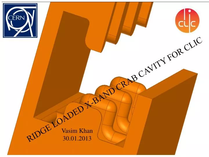
RIDGE LOADED X-BAND CRAB CAVITY FOR CLIC Vasim Khan 30.01.2013
CLIC crab cavity – base line design Racetrack cell shape Courtesy of G. Burt, et. al.
Ridge loaded waveguide structures: Rama Calaga http://indico.cern.ch/conferenceDisplay.py?confId=178008 Double ridged 2 cell cavity: 12GHz SW cavity Efield @ mode 4.0 mm 12.9 mm 25 mm Three Concepts for LHC Quarter wave 4-rod cavity Double ridged I. Ben-Zvi et al. J. Delayen et al. G. Burt et al.
Ridge loaded crab cavity : f=12 GHz & ϕ = 2π/3 t/2 rz Beam a Beam (z) Ey rx/2 Hx
Ridge loaded crab cavity : f=12 GHz ϕ= 2π/3 Nc=15 Beam offset = 0.4 mm a = 3.0 mm a=5.0 mm Vt= 2.55 MV ϕ= 2π/3 Nc=15 Vt= 2.55 MV -- Unloaded - Loaded ϕ= 5π/6 Nc=12 a = 2.5 mm • Circular shape of the cavity may not be so efficient! • Need to reduce vg without much change in R/Q
Rectangular cell: One extra handle to tune χ where the parameter needs to be minimised is t/2 rx rz Beam (z) Beam (z) 2a Y ϕ = 2π/3 Nc=15 Vt= 2.5 MV Beam offset = 0.4 mm -- Unloaded - Loaded X Z
Optimisation scan ϕ = 5π/6 Nc=12 Et = 20 MV/m Vt= 2.5 MV t=6.0 mm
Un-damped const. imp. structure 16.5 • Loaded • -- Unloaded ϕ = 2π/3 Nc = 15 Et = 20 MV/m Vt= 2.55 MV Beam offset = 0.4 mm 16.2 Target for (ΔV/V =0.5 %) => χ = 2770 ϕ = 5π/6 Nc = 12 Et = 20 MV/m Vt= 2.55 MV VT=2.55 MV
Waveguide damping F=11.99 GHz Q=3246 θ = 150 deg vg/c=2.8 % R/Q=125 Ω χ = 693 (m2/Ω/sec) Φ=150 deg. X=9.38 mm t=6 mm rx/x=40% F=12.8 Q=25 θ = 166 deg WGW= 12 mm WGH= 40 mm CW= 8 mm CH= 1 mm
5π/6→HPA const. imp. damped structure 20.9 20.1 19.5 18.1 VT=2.55 MV ΔV/V=0.51 % Tp=240.5 ns 15.8 14.6 147.2 141.6 Solid curves: Beam loaded Dashed curves: Unloaded Beam offset = 0.4 mm 2.3 2.1
First HOM Fundamental Dipole mode E-field @ 12.9 GHz E-field @ 12 GHz HPA Y X Field between the ridges Φ=150 deg.
HPA: Full structure simulation Y Z 1 E-field @ 12.9 GHz Envelope wake Beam→ Wake with phase information
Using symmetry planes EH : 12 GHz HH : 12.91 GHz XY : F Y X E-field EE : 23.0 GHz HE : 17.33 GHz
Quarter symmetry structure Beam offset =0.5mm
2π/3→SPA Beam offset =0.5mm 22.2 21 20.3 20.1 VT=2.55 MV ΔV/V=0.51 % Tp=240.5 ns Solid curves: Beam loaded Dashed curves: Unloaded 165.6 158.6 15.85 14.5 2.87 2.64 Beam offset = 0.4 mm
Summary * To be checked
Remarks • There is no obvious difference between SPA and HPA ridge cavities • Input power requirement is comparable to the base-line design • Pulsed temp rise seems to be comparable, surface E-field is higher • Almost no contribution from the higher order dipole modes • HOMs still need to be investigated carefully! • Longitudinal wake seems just on the edge of the acceptable limit. • Detailed beam dynamics calculations to be done for beam stability • Further development in the structure: subject of discussion Acknowledgements Many thanks to Rama Calaga for suggesting this topic and AlexejGrudievfor his guidance! Also thanks to Praveen Ambattuand Graeme Burt for updates on the base-line design! Thank you!
First HOM Fundamental Dipole mode E-field @ 12.9 GHz E-field @ 12 GHz HPA Y X Field between the gaps
ϕ = 2π/3 Nc=15 Vt= 2.5 MV Eacc = 20 MV/m 172 143 161 150
HPA Beam offset =0.0 Beam offset (Y) =0.5mm Full structure Beam on axis Envelope wake Envelope wake Wake Wake
ϕ = 2π/3 Nc=15 Et = 20 MV/m Vt= 2.5 MV t=2.0 mm
Quarter symmetry structure Beam offset =0.5mm
The WG mode E-centre E-centre E-front F=12.5 Q=160 R’/Q=434 Ω/m (on axis) =465 Ω/m (0.5m off) θ = 159 deg
HPA Full structure Beam on axis 12.94 • Wx • Wy • Zx • Zy 14.45 16.4 Envelope wake Wake
HPA Full structure Beam offset =0.5mm 11.9 • Zx • Zy • Wx • Wy 12.9 Envelope wake Wake
SPA SPA Full structure Beam on axis
SPA Full structure Beam offset =0.5mm
SPA • HPA HHBC offset = 0 mm
offset = 0.5 mm HHBC
Only dipole modes: EHBC quarter symmetry • Off set = 0.25 mm • Off set = 0.5 mm HPA HPA
Target : χ = 2770 => ΔV/VT = 0.5% Quarter symmetry cell HHBC Monopole and quadrupole Beam on axis : Offset = 0.0 mm
Quarter symmetry cell HHBC Monopole and quadrupole Beam offset = 0.5 mm
ΔE/E0 < 10-6 ΔE/E0 < 10-6 EHBC , HHBC?
Offset = 0.5 mm • EHBC • HHBC • HEBC • EEBC-X • EEBC-Y
What we need ? or For Nc= 15 @ 120 deg ph. adv. Can we calculate require power same as we do in acc. str. ? Units don’t match for the third term They do after some correction Is it correct though?