CLIC Crab Cavity Specification and Synchronisation Requirements
290 likes | 313 Vues
Learn about the CLIC crab cavity specification, design process, cell testing, high-power tests, and RF synchronization. Get insights into the planned CLIC crab cavity tests and manufacturing details. Understand the importance of beamloading management and cavity synchronisation for optimal performance.

CLIC Crab Cavity Specification and Synchronisation Requirements
E N D
Presentation Transcript
CLIC Crab Cavity Praveen Ambattu, Graeme Burt, Amos Dexter, Ben Woolley, Valery Dolgashev, Peter McIntosh, Philippe Goudket, Roger Jones, Alexej Grudiev, Vadim Soldatov, Germana Riddone, Igor Syratchev. CLIC UK collaboration meeting CERN May 2012
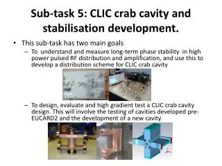
Combined Project Scope • REMAINING EUCARD1 TASKS (FP7) • Gradient tests of a cell design excited in a dipole mode at SLAC • (Awaiting delivery from Shakespeare Engineering) • Manufacture a multi-cell un-damped cavity for high power tests at CERN • (Disc manufacture is proceeding) • Complete phase measurement sampling electronics • (Will complete by August) • UK-CERN CLIC COLLABORATION PROJECT • Development of a damped structure with racetrack/elliptical cells • (on going) • Engineering design work to enable prototype cavities to be tests at CERN • (cooling, vacuum, mounting, instrumentation etc.) • Experiments to understand stability of the RF distribution system • (PhD project starting with RF measurements on CTF3 use dog leg) • R&D as necessary to improve stability of RF distribution system • (Some new ideas to present)
CLIC crab cavity specification • Transverse space: ~1 m • Bunch rotation angle: 10 mrad • Travelling wave mode: 2p/3, 11.9942 GHz • Voltage: 2.55 MV per cavity • Available peak power at cavity: 14 MW • Max peak surface field (absolute) 250 MV/m • Max peak pulsed heating: 40 K • RF tolerances for 98 % luminosity: dVrf / Vrf=2 %, dfrf=22 mdeg with vertical B field on axis, phased for zero B at bunch centre Use TM110h pillbox crabbing mode The design process must also meet wakefield specifications and have a means to manage unpredictable beamloading
Cavity synchronisation CLIC bunches ~ 45 nm horizontal by 0.9 nm vertical size at IP. Cavity to Cavity Phase synchronisation requirement So need RF path lengths identical to better than c Dt = 1.3 microns
Beamloading and cell number Manage beamloading by having high power flow or dissipation much high than expected loading Can increase power convection by increasing the structure group velocity. The group velocity depends on iris radius. But have limited power (~15 MW) at cavity so can only increase the convection so much. Ten cells is about about the minimum
Planned CLIC crab high power tests Travelling wave 11.9942 GHz phase advance 2p/3 TM110h mode Input power ~ 14 MW Test 1: Middle Cell Testing – Low field coupler, symmetrical cells. Develop UK manufacturing. Test 2: Coupler and cavity test – Final coupler design, polarised cells, no dampers. Made with CERN to use proven techniques. Test 3: Damped Cell Testing – Full system prototype
Prototype 1 – UK Built The 1st CLIC crab cavity prototype has been manufactured by Shakespeare Engineering in the UK. Tolerance and surface roughness on single parts have been measured and are acceptable. Waiting for flanges to be brazed.
CLIC detector halls Crab cavity klystron Have had meeting with MDI group (23rd Oct 2011) to discuss the location of the klystron and waveguides in the IP region. Overmoded waveguide from magic tee to klystrons ~35m of waveguide from the Tee to the cavities
RF and sync to beam travelling wave cavity Control Main beam outward pick up Magic Tee Waveguide with micron-level adjustment Waveguide with micron-level adjustment LLRF LLRF Phase Shifter From oscillator 12 GHz Pulsed Klystron ( ~ 50 MW ) 12 GHz Oscillator Pulsed Modulator Vector modulation Control main beam outward pick up Estimate of bunch to RF synchronisation ~ 100 fs (0.43 degrees) Once the main beam arrives at the crab cavity there is insufficient time to correct beam to cavity errors. 0. Send off frequency pre-pulse and measure phase difference of reflections 1. Perform waveguide length adjustment at micron scale 2. Measure phase difference between oscillator and outward going main beam 3. Adjust phase shifter in anticipation of round trip time and add offset for main beam departure time 4. Klystron output is controlled for constant amplitude and phase 5. Record phase difference between returning main beam and cavity 6. Alter correction table for next pulse
RF path length measurement Power Meter Power Meter -30 dB coupler -30 dB coupler 48 MW 11.994GHz Klystron 200 ns 50 Hz rep. Cavity Cavity Cavity Coupler 0dB or -40dB reflection Cavity Coupler 0dB or -40dB reflection Power Meter RF Phase Measurement System 12 MW -30 dB coupler Magic Tee Lossy Waveguide (-3dB) Lossy Waveguide (-3dB) Phase shifter Phase shifter Main pulse reflection ~300 W Measurement pulse return 1kW 8 kW 11.8GHz Klystron 5 μs pulse 5 kHz rep.
Phase measurement accuracy Accuracy depends on measurement bandwidth due to noise limitations (bandwidth determines minimum measurement time). Table below shows data for a single mixer + amplifier with 14 dBm power input: can use 4 to double accuracy and use more power. High Speed op amp Double balanced mixer Reflection from cavity 1 Variable LPF Voltage to oscilloscope /ADC Reflection from cavity 2
Cavity reflection with frequency Measurement pulse@11.8GHz, ≈100% reflection Normal Operation @11.994 GHz, -45dB reflection
Waveguide choice Rectangular invar is the best choice as it offers much better temperature stability-> Expands 2.3 microns for 35 m of waveguide per 0.1 °C.
LLRF Hardware Requirements • Fast phase measurements during the pulse (~20 ns). • Full scale linear phase measurements to centre mixers and for calibration. • High accuracy differential phase measurements of RF path length difference (5 μs, 5 kHz). • DSP control of phase shifters. Linear Phase Detector Amp + LPF 10.7GHz Oscillator DBM DBM ADC Amp + LPF ADC DSP DBM DAC Wilkinson splitters -30 dB coupler -30 dB coupler To Cavity Magic Tee To Cavity Manual phase shifter for initial setup Fast piezoelectric phase shifter Prototype systems have been developed.
-30 dB coupler Proposed CTF dog-leg experiment • Use klystron, slide tuner and magic tee to determine the phase stability of the CTF WG dog-leg. RF Phase Measurement System -30 dB coupler Cavity OR short Δ port port1 port 2 CTF dog-leg Sliding short with micron level adjustment -30 dB coupler Σ port • Compare reflections from cavity/short at the magic tee using: • Power radiated from the Δ port. • Phase measurement system attached to couplers. Klystron
Wakefield calculations for cylindrical cavity 3D Eigen mode simulations were performed in Microwave studio for the first two vertical, horizontal and monopole pass-bands including input/output couplers. • The largest kick factor of any vertically polarised dipole mode is the 2p/3 mode in the SOM pass band (kt=1.2 V/pC/mm). • The highest kick factor of a HOM is only 0.27 V/pC/mm. Three modes in the SOM pass band have higher kick factors. • Hence the SOM pass band dominates the vertical wake. SOM passband (freq and Kick factor) • Initially we worked on the assumption that all modes would be damped equally. • This lead to a very stringent damping tolerance for a Q of 125. • We assume a static offset of 35 microns (tolerance ~8.5 V/pC/mm). • The required Q factors drop significantly as the static offset increases. If we assume a 0.1 mm offset we need to damp the SOM to a Q of 100. SOM x HOM damping Sum wake x Q Offset x Q
Waveguide damping Crab Dip3_vert LOM Dip3_hor SOM SOM Horizontal HOM SiC load (13-j0.16) WR112 WR42 We can use a waveguide to damp the horizontal HOM’s as well as long as the crab is below cut-off
Single mode sum wakefield • If a single mode excitation by the beam is assumed, the sum transverse wakefield yields the function shown in the figure • This is nearly true because the SOM dominates the vertical wakefield • At Df=0, the kick is zero but this point is close to the maximum wake as there is maximum energy in the cavity • At +/- 1GHz, every bunch cancels the field induced by the previous bunch and wake is again zero • This suggests the use of asymmetric cell shape to detune the SOM to 13 GHz • At 13 GHz, all the modes in the pass band are far from resonance hence the required damping is reduced significantly from that of a symmetric cell shape 4 5 5 5 5 5 5
Racetrack cell-surface fields Esurf Ssurf=(ExH)surf • Dipole fields are quite different from accelerating field • Peak electric and magnetic fields of the dipole mode are located 90 degrees from each other on the iris • Surface Poynting flux Ssurf is however at 45 deg to both E and H • Location of the breakdown on the iris provides critical information about the role of magnetic field in breakdown • The cavity has a large Sc but relatively low E and H fields at the surface so this also provides an independent verification of new CERN theory. Hsurf CI-SAC Dec 2011
Undampedvs damped cell Rx Ry Racetrack cell Waveguide damped Ry/Rx=1.207, fcrab=12 GHz, fsom=13 GHz No major changes in RF properties with cell shape or damping
Coupler Options Mode launcher Standard Waveguide We investigated Standard, Waveguide and Mode launch couplers
Coupler properties Mode launcher coupler Useful cavity length Waveguide coupler Standard (compact) coupler Surface fields for 12 cells, 2.55 MV kick • coupler type doesn’t make a difference in the surface fields • Because peak E and H fields lie on the irises for a dipole cavity • So performance is not limited by the coupler heating • We chose standard couplers for now as it is the most compact
Dual feed coupler • Field has perfect symmetry about the coupler forcing the monopole component to essentially zero • But needs two splitters which increases structure complexity and may have impact on phase stability • Difficult to tune and damp end cell Ez absEz x y @ end cell
Single-feed coupler Shorted dummy guide (1) Standard single-feed (2) Single-feed with dummy waveguide
Single feed coupler absEz x r in endcell for 1 W Multipole components rad, mm (on-axis) (1 mm off-axis) (1mm off-axis) rad, mm • The coupler gives rise to a monopole (and higher order multipole) component in the endcells • For 2.55 MV dipole kick, the corresponding monopole kick is 62 kV which is unwanted • Rotating the couplers by 180 deg reduces the monopole kick to 8.7 kV but doesn’t cancel, as this component is out of phase with the dipole • Small adjustment of the endcell length adjusts the beam phase which reduces the monopole kick to a few tens of volts
With dummy waveguide Multipole components absEz x r in endcell for 1 W (on-axis) (1 mm off-axis) (1mm off-axis) rad, mm • Dummy waveguide reduce the monopole component in the end cells by about 3 times • The dummy guide width can be fine adjusted for phase adjustment of the monopole to reduce the kick voltage to a few 10s of volts • As the present prototype doesn’t see a beam, we chose not to use the dummy guide
Parameters for un-damped prototype Drawings done at CERN and manufacture is progressing at VDL
Cavity tuning • Pins attached at 45 deg to the racetrack cell will help frequency tuning • Field measurement using bead pull followed by non-resonant perturbation technique will help matching the structure in a few iterations Endcell DS11=S11p−S11u = −jwkF2/2Pin Pin=input power S11p/u=perturbed/unperturbed complex reflection coefficient at input coupler F=Field quantity perturbed by the bead Beadpull simulation with metallic disk, 1.5 mm dia, 0.5 mm thickness Regular cell Complex DS11 |DS11|x bead pos • T.Khabiboulline, A new tuning method for travelling wave structures, PAC95 • J. Shi et.al, Tuning of CLIC accelerating structure prototypes at CERN, LINAC10
Summary • Cavity development/testing • Awaiting gradient tests of a cell design excited in a dipole mode at SLAC. • Ongoing manufacture of a multi-cell un-damped cavity for high power tests at CERN. • Ongoing design of a multi-cell damped cavity. • RF distribution system development • Ongoing design/manufacturing of measurement sampling electronics. • Experiments to understand stability of the RF distribution system presented. • R&D as necessary to improve stability of RF distribution system presented.