Download

1 / 17
170 likes | 295 Vues
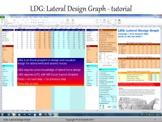
LDG is an Excel program to design and visualize design for lateral wind and seismic forces LDG requires some knowledge of lateral force design LDG requires a PC with MS Excel macros Enabled Press > for next step, < for previous step Press Esc to end. Ly. Ly. Ly. Ly. Lx. Lx. Lx. Lx.

E N D
LDG is an Excel program to design and visualize design for lateral wind and seismic forces LDG requires some knowledge of lateral force design LDG requires a PC with MS Excel macros Enabled Press > for next step, < for previous step Press Esc to end
Ly Ly Ly Ly Lx Lx Lx Lx LDG computes floor area A = (Lx Ly) assuming rectangular plans. to get correct seismic values, prorate dead load to represent the actual floor area. For example, if the floor area of a plan is 30% smaller, reduce the dead load 30% Ly Lx
Enter design factors prior to running LDG Seismic data brown Wind data green Velocity Pressure Coefficient Kz = Exposure factor Copy columns TU into AB as default if needed Data position is critical for LDG to run properly
20 Press Ctrl-Shift-R to start LDG (Excel macro) Select input type: 0, 1, 2, or 3 0 = as is, run current structure displayed or as modified 1 = uniform: floors, story height, and mass 2 = tapered: changing from base to top 3 = custom: unique floors or stacks of floors Then input (for 1, 2, 3 only): Number of levels Level length (ft) Level width (ft) Story height (ft) Mass (Dead Load in psf = pounds / ft2) Input Importance factors
Lateral loads - acting primarily horizontally are: Wind load Seismic load Earth pressure on retaining walls (not in LDG)
Fa factors, IBC Table 1615.1.2 [1] (low-rise) Sds = (2/3)(Fa SS) [Ss = top line] Fv factors, IBC Table 1615.1.2 [2] (high-rise) Sd1 = (2/3)(Fv S1) [S1 = top line] Importance factors Press Ctrl-Shift-R to run LDG US wind velocity map
Seismic Design V = Cs W = seismic base shear (lateral force @ building base) W = mass = (DL + 25% storage LL) CS = I Sds / R [seismic equation for T<TS] CS = I Sd1/(RT) [for T>TS<TL] CS = I Sd1 TL / (RT2) [for T>TL] I= Importance Factor [see slide 1] Sds = (2/3)(Fa SS) [see Fa table - low-rise] Sd1 = (2/3)(Fv S1) [see Fv table - high-rise) TS = Sd1/Sds [see Spectrum @ left] T ~ 0.1(# stories) [building period = cycles/second] SS & S1 [see USGS Table] R = R-factor [see IBC Table 1617.6.2] TL = Time Laps [range 4 -12, ASCE7 Fig 22-15] Note: CS ~ 0.03 for high-rise moment frames CS ~ 0.15 for wood structures CS ~ 0.30 for masonry structures W = w A [A = floor area] w ~ 25 psf for wood structures w ~ 70 psf for steel structures w ~ 150 psf for concrete structures
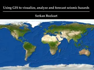
USGS seismic factors USC: SS = 1.85 (low-rise), S1 = 0.64 (high-rise)
Wind Design V = p A = wind base shear (lateral force @ building base) p = wind pressure (in psf = pounds / square foot) A = exposed tributary area p = wind pressure(psf) p = 0.00256 V2 I Cp G Kd Kz Kzt V = velocity (mph) I = Importance Factor (see slide 1) Cp = external pressure coefficient Cp = 0.8 windward Cp = 0.2 to 0.5 leeward G = Gust factor G = 0.85 for rigid structures G = 1.3 - 1.5 for fabric structures Kd = 0.85 for buildings [directionality factor] Kz = 2.01 (Z/Zg)2/ Z = height above ground Exposure Zg B Inner city 1200 7.0 C Open area 900 9.5 D Near ocean or lake 700 11.5 Kzt = Velocity Factor = 1 for flat sites
Wind pressure (IBC/ASCE 7 Method 2, Analytical Procedure) p = qGCp–qi(GCpi) [minimum p = 10 psf (480 Pa)] q velocity pressure (defined below) qz for windward wall (evaluated at height z above ground) qh for leeward wall (constant, per mean roof height h) G gust factor (Rigid G=0.85, fabric structure G=> 1.2) GCpiInternal pressure (± 0.18for enclosed structures) Cp pressure coefficient (from ASCE 7 figures and tables) Cp = 0.8 (windward walls) Cp = - 0.2 to - 0.5 (leeward walls) Cp = - 0.3 to + 0.4 (for roofs) q= 0.00256 I KzKztKdV2 (q = velocity pressure in psf) V = wind speed, mph (IBC Fig. 1609, or local speed) I = Importance factor (IBC table 1604.5) I = 1 (all structures not listed below) I = 1.15 (hospitals, police and fire stations, etc) I = 0.87 (agricultural and temporary facilities) KZt Topography factor (KZt = 1 for regular sites) Kd Directionality factor (Kd= 0.85 for most structures) KZ Exposure factor (graph at left, min. 0.7 for gladding) B = Exposure B (inner city, protected) C = Exposure C (open area, unprotected) D = Exposure D (near ocean or large lakes) Graph see Structure and Design page 577
Optional select and copy (Ctrl C) data to make graphs at another sheet or make graphs on this Excel sheet
Select a chart type Paste selected data into another Excel sheet Select data
Fwx &Vwx (k) Fwy &Vwy (k)