Download

1 / 44
440 likes | 533 Vues
Explore the flaws in current tidal turbine designs and discover potential solutions for increased efficiency and reduced environmental impact. Learn about innovative technology and considerations for optimal performance in marine energy generation.

E N D
Are Nearly all Tidal Stream Turbines Designs Wrong? Stephen Salter Institute for Energy Systems University of Edinburgh S.Salter@ed.ac.uk www.see.ed.ac.uk/~shs
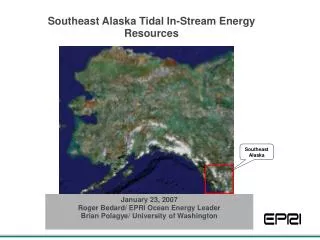
Cells are 1 minute of arc lat. 1.5 minutes long = 2.617 km2. Power = 6.165 TW x Cf Courtesy Proudman Labs
Peak spring Pentland sea-bed friction = 6.165 TeraWatt x Cf But what is Cf ?
From Black and Veatch 2011. Using values for the Pentland Firth U = 3m/s, ρ = 1025 kg/m3, channel length = 23 km, channel width = 10 km in combination with a more appropriate bed friction coefficient CD = 0.0015 energy dissipated due to bed friction averaged over a tidal cycle calculated is 4.05 GW.
Laminaria Hyperborea (kelp) are found along the edges of the Pentland Firth at depths up to 30 m. Length can reach 3.5 metres. Cf = ?
68 mm bob Pentland bed stills. P Hayes. Fisheries Research Aberdeen 2006-8
6.165 TeraWatt x 0.04 = 247 GW X 0.38 = 93.7 GW at peak spring
O’Doherty DM. Mason-Jones Morris, O’DohertyT, Bryne, Pricket, Grosvenor. Interaction of marine turbines in close proximity. EWTEC 2011
EWTEC Patras 1998 Edinburgh vertical-axis, variable pitch with rim power take off.
R.A. McAdam , G.T. Houlsby , M.L.G. Oldfield Structural and Hydrodynamic Model Testing of the Transverse Horizontal Axis Water Turbine EWTEC 2011
Speed up x 30 Range up x 6000 Payload up x 20,000 Cost down ÷ 100
Variable pitch advantages Easy tow to installation site with 2.5% drag of circular members Agile self propulsion Instant disconnection of delivered power Relief of bending stress in rings Avoidance of cavitation Double performance at lower tip speed ratios for 1.5% extra cost Online conversion from open flow field to close packed Survivor repulsion Sibling assistance Reactive loading to tune Pentland Firth to M2 Potential for delayed generation
Problems for horizontal-axis axial-flow rotors Lower efficiency near the hub. Low packing-fraction means poor use of resource. Longer power cables. Higher bending moments at the blade roots. Coincidence of shear and bending stress. Vortex shedding at blade tips. Tower leverage. Hydrodynamic wake pollution. Sensitivity to flow direction change. Volume constraint for pitch mechanism. Betz limit. Bearing leverage. Bending moments limit power rating. Hydrostatic pressure variation. Submerged power-conversion mechanism. Lack of space for power conversion. Submerged main bearings. Less power smoothing. More expense for tapered and twisted hydrofoils. No bridge option. Need for high rubbing seal velocity . . . . . . . . . . . . .
S.Salter@ed.ac.uk www.see.ed.ac.uk/~shs