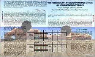
Physical Models Used (and Not Used) in GNSS Data Processing
1.43k likes | 1.57k Vues
Physical Models Used (and Not Used) in GNSS Data Processing. Dr. Mark Schenewerk Mark.Schenewerk@noaa.gov 816-994-3009. 2. 2011-11-03. Who is this guy?. I am Mark Schenewerk with National Geodetic Survey (NGS).

Physical Models Used (and Not Used) in GNSS Data Processing
E N D
Presentation Transcript
Physical Models Used (and Not Used) in GNSS Data Processing Dr. Mark Schenewerk Mark.Schenewerk@noaa.gov 816-994-3009
2 2011-11-03 Who is this guy? I am Mark Schenewerk with National Geodetic Survey (NGS). B.S. from the University of Missouri at Rolla.Ph.D. from the University of Illinois at Champaign-Urbana. The NGS calls me a geodesist, but I’m actually an astronomer who happens to do things that look like geodesy. I am the “father” of the PAGES processing software. I’ve been (very) indirectly involved in OPUS since its inception and directly involved in some of the new development for the last few years.
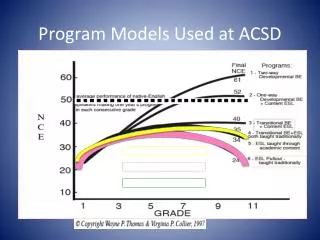
3 2011-11-03 Workshop Outline • Introduction • Reference frames • Clock Errors • PPP, DGNSS and Double-differencing • Correlations • Antenna Phase Center Variations • Phase Wrapping • Observation Elevation Weighting • Charged and Neutral Atmospheric Delays • Solid Earth Tide • Ocean Tide, Atmosphere and Other Surface Loading • Subsidence and Rebound • Data Span Versus Accuracy • When Good Data Goes Bad
4 2011-11-03 • The effect on “real” data? I wanted to compliment these discussions with processing results using real data. For this, I needed a test network that: • provides a reasonable representation of the GPS hardware. • provides at some commonly encountered baseline lengths. • is reliable so that I can create time series of results sufficient for identifying problems and characteristics of the included sites and their data. • is sufficiently small thereby permitting me to process its data quickly and in a variety of ways.
5 2011-11-03 • The Test Network I opted for 2002-090 through 2002-103 data from a subset of the Ohio CORS. A few other sites will be used for special cases. This networkcan be used to make baselines 23.4 to 428 km.Even thousandsof kilometers if the“other” sites areconsidered.
6 2011-11-03 • The Test Network’s Hardware These are the site designations and antennas identifiers. SITE ANTENNA algo - "AOAD/M_T "; IERS ITRF2000 aoml - "AOAD/M_T "; IERS ITRF2000 nlib - "AOAD/M_T "; IERS ITRF2000 colb - "TRM29659.00 " defi - "TRM29659.00 " erla - "ASH700936C_M "; IERS ITRF2000 freo - "TRM29659.00 " galb - "LEIAT303 LEIC"; IERS ITRF2000 gust - "TRM29659.00 " leba - "TRM29659.00 " mcon - "TRM29659.00 " pktn - "TRM29659.00 " sidn - "TRM29659.00 " stkr - "ASH700718B " tiff - "TRM29659.00 " woos - "TRM29659.00 "
7 2011-11-03 • Linearization Bear in mind that almost all data processing assumes that, in some regime, data can be approximated by a straight line. If the data can not be approximated in this way, the modelling error intrudes corrupting the results.
8 2011-11-03 • Global Navigation Satellite System GNSS, the acronym for Global Navigation Satellite System(s), is a sweeping term for Global Positioning System or GPS (USA), GLONASS (Russia), Galileo (EU), Compass (China) and others to come. All these systems are broadly very similar although they differ in detail. Organizations build and launch satellites broadcasting signals that small, light, rugged, inexpensive receivers can freely use 24/7. You don’t have to do anything! That’s a great deal so it’s no surprise that GNSS technology has permeating so many aspects of our culture.
9 2011-11-03 • GNSS Past and Future GPS and GLONASS began development in the 1970s. Launches began in the 1980s with at least one complete system in operation since the early 1990s. The U.S. Department of Commerce estimates that billions of dollars of GNSS equipment are sold annual and that the total value of these systems to the users is tens of billions of dollars. www.pnt.gov/public/1997-2004/2003-12.../csis2003-bogosian.ppt geodesy.noaa.gov/PUBS_LIB/Socio-EconomicBenefitsofCORSandGRAV-D.pdf Next generation GPS and GLONASS satellites are being tested, as is Galileo and Compass technology. GNSS will be available for the foreseeable future.
10 2011-11-03 • Let’s test the waters. As simple to use and great a value as GNSS is, if you’re willing to know a bit more, you can get better results making it a better value. That’s why we’re here, so let’s dip a toe in. Here’s how GNSS positioning works in six slides.
11 2011-11-03 • How GNSS works in 6 slides. (1/6) A GNSS satellite passes overhead broadcasting a signal: I’m SV 1 at XYZ1 (1) at Time1(1). I’m SV 1 at XYZ1 (2) at Time1(2). I’m SV 1 at XYZ1 (3) at Time1(3). • • •
12 2011-11-03 • How GNSS works in 6 slides. (2/6) At the same time, other satellites are saying: I’m SV 2 at XYZ2 (1) at Time2(1). I’m SV 3 at XYZ3 (1) at Time3(1). I’m SV 2 at XYZ2 (2) at Time2(2). I’m SV 3 at XYZ3 (1) at Time3(2). I’m SV 2 at XYZ2 (3) at Time2(3). I’m SV 3 at XYZ3 (1) at Time3(3). • • • • • •
13 2011-11-03 • How GNSS works in 6 slides. (3/6) Your receiver hears all this just a fraction of a second later: SV 1 said its at XYZ1 (1) at Time1(1), but I think it is TimeA(1). SV 2 said its at XYZ2 (1) at Time2(1), but I think it is TimeA(1). SV 3 said its at XYZ3 (1) at Time3(1), but I think it is TimeA(1). • • •
14 2011-11-03 • How GNSS works in 6 slides. (4/6) Your receiver knows that these signals are travelling at the speed of light, c, so it starts doing a some math: c × (TimeA(1) – Time1(1)) means I’m RangeA1(1) from XYZ1(1). c × (TimeA(1) – Time2(1)) means I’m RangeA2(1) from XYZ2(1). c × (TimeA(1) – Time3(1)) means I’m RangeA3(1) from XYZ3(1). • • •
15 2011-11-03 • How GNSS works in 6 slides. (5/6) If your receiver has enough ranges, then it can compute its position: XYZA(1) at time TimeA(1). Repeat ad nauseum.
16 2011-11-03 • How GNSS works in 6 slides. (6/6) Now you have a choice. You can have the receiver report is position moment by moment, i.e. kinematic, or average its results over time, static, giving a more accurate position.
17 2011-11-03 • It’s simple, but not quite that simple. We all know that it is not quite that simple, but that covers the basics: • Satellites carrying clocks orbit the Earth broadcasting their positions with a time tag. • A specially designed receiver with a clock captures the time-tagged positions from some or all satellites. • Using these observations and some knowledge about physical world, the receiver can compute its position instantaneously or as a time-averaged mean. If that didn’t scare you off, then let’s jump into the deep end and get some important, but boring stuff out of the way.
18 2011-11-03 • GNSS Carrier Frequencies Focusing on the two operating systems for the time being: GPS and GLONASS. Both broadcast on two carrier frequencies GPS: 1575.42 MHz (19.03 cm wavelength) 1227.60 MHz (24.42 cm wavelength) GLONASS: 1602.00 MHz (18.71 cm wavelength) 1246.00 MHz (24.06 cm wavelength) Common jargon identifies these as the L1 and L2 GPS and GLONASS frequencies.
19 2011-11-03 • GNSS Signals The carrier frequencies carry information. GPS: A digital signal that identifies the satellite, Course Acquisition and Precise time information plus other information about the positions of and clock corrections for itself and sister satellites. GLONASS: A slight frequency shift that identifies the satellite and a digital signal containing Course Acquisition and Precise time signals, and other information about the frequency offsets, positions of and clock corrections for itself and sister satellites.
20 2011-11-03 • Pseudoranges The Course/Acquisition or C/A code offers low precision, but is a quick way to begin interpreting the Precision or P code. Correctly interpreting these codes gives the time the signal was transmitted. Knowing the transmit and receipt times means the receiver can compute a range to the satellite. Range = c × (Time(receipt) – Time(transmit)) But these ranges still contain unmodelled clock errors (we’ll talk about this in a bit) and so are called pseudoranges to help distinguish their character.
21 2011-11-03 • Broadcast Message The satellite positions, clock corrections and a few other items are also encoded on the GNSS signal. Collectively, these are called the broadcast message. As we’ve seen with our simple example, the time signals plus the broadcast message are everything a receiver needs to compute ranges to the satellites and determine its position.
22 2011-11-03 • Phases The receiver also tracks the phase of the carrier signal. Measuring the phase of the carrier frequency can be done at a small fraction of a wavelength. This means that phase measurements have the potential to be significantly more precise than pseudorange measurements.
23 2011-11-03 • Integers But the receiver doesn’t know how many wavelengths can “fit” in the distance between itself and the broadcasting satellite. It only knows how many have passed since it began tracking. Without knowing these integer wavelength counts, or more simply integers, the receiver can’t use the phase directly for ranging to the satellites. Determining the integers requires external information, time spent continuously observing a satellite or both.
24 2011-11-03 • How do I get all these observations? Folks don’t need to in most cases, but it is possible to use this information after the fact to compute positions even more accurately. This is called post-processing. To facilitate post-processing, receivers can produce files with this observation information. There are numerous formats for this information. The one most commonly used for high-precision post-processing and the only one mentioned here is called the RINEX or Receiver INdependentEXchange format. igscb.jpl.nasa.gov/igscb/data/format/
25 2011-11-03 • A Quick Summary The satellites broadcast L1 and L2 signals. From these signals, the receiver can compute or measure the L1 and L2 pseudoranges and phases. With the pseudoranges and the broadcast message, a receiver can determine its position with limited accuracy. With other information it can compute its position more accurately or you can do so after the fact in post-processing. With the phases, integers and the broadcast message or other information, the receiver can compute its position still more accurately or you can do so after the fact in post-processing.
26 2011-11-03 • The Celestial and Terrestrial Frames Because GNSS involves satellites tracked by ground stations, GNSS data processing must be expressible and consistent in two spatial frames: • the celestial or inertial frame, and • the terrestrial or Earth-centered, fixed (ECF) frame. But what does this jargon really mean?
27 2011-11-03 • The Celestial Frame The celestial frame describes the Earth as it looks from far above. In this frame we, the observers, watch our world rotate as it orbits around the Sun. The Moon travels with the Earth and completes its orbit in a little less than a month. Likewise, the GNSS satellites travel with the Earth orbiting it twice per day. The equations describing the motions and interactions of these bodies are much simpler in this frame. nssdc.gsfc.nasa.gov/image/planetary/earth/gal_earth_moon.jpg
28 2011-11-03 • The Terrestrial Frame The terrestrial frame describes the Earth as looks to an observer on the Earth’s surface. In this frame, the Earth appears stationary while the Sun, Moon and satellites pass overhead. This is in the frame that we “see” every day. And it is in this frame we ask questions like what are the coordinates of this point? What are the distances and directions to other points? How fast is this point moving relative to other points? apod.nasa.gov/apod/image/0906/moonrise_sisman_orig.jpg
29 2011-11-03 • Celestial and Terrestrial Link The connection between these two frames is dominated by stable processes. The Sun, Earth, Moon and satellites seem to move in the same way day after day. But if we look more closely, other processes are involved too. Our irregular, slightly flattened Earth suffers • Precession. • Nutation. • Changes in its rate of spin. • Changes in the orientation of its spin axis. These motions are expressed as 6 x 6 rotation matrices (position and velocity) and are the link between the terrestrial and celestial frames.
30 2011-11-03 • Celestial and Terrestrial Frames The connection between these two frames is dominated by stable processes. The Sun, Earth, Moon and satellites seem to move in the same way day after day. But if we look more closely, other processes are involved too. Our irregular, slightly flattened Earth suffers • Precession. • Nutation. • Changes in its rate of spin. • Changes in the orientation of the its spin axis. These motions are expressed as 6 x 6 rotation matrices (position and velocity) and are the link between the terrestrial and celestial frames. The gravitational attraction of the Sun, Moon and planets cause the spinning top that is the Earth to precess, or slowly wobble, just as a toy top does under the influence of the Earth's gravity. The magnitude of this change is about 20 arcsec (620 meters) per year, but very stable and very accurately modelled.
31 2011-11-03 • Celestial and Terrestrial Frames The connection between these two frames is dominated by stable processes. The Sun, Earth, Moon and satellites seem to move in the same way day after day. But if we look more closely, other processes are involved too. Our irregular, slightly flattened Earth suffers • Precession. • Nutation. • Changes in its rate of spin. • Changes in the orientation of the its spin axis. These motions are expressed as 6 x 6 rotation matrices (position and velocity) and are the link between the terrestrial and celestial frames. The gravitational attraction of the Sun also slowly precesses the Moon's orbit. This variation in the Moon's orbit in turn causes a variation in the orientation of the rotation axis of the Earth. This variation is called nutation and has an amplitude of about 9 arcsec (270 meters). Nutation is very accurately modelled.
32 2011-11-03 • Celestial and Terrestrial Frames The connection between these two frames is dominated by stable processes. The Sun, Earth, Moon and satellites seem to move in the same way day after day. But if we look more closely, other processes are involved too. Our irregular, slightly flattened Earth suffers • Precession. • Nutation. • Changes in its rate of spin. • Changes in the orientation of the its spin axis. These motions are expressed as 6 x 6 rotation matrices (position and velocity) and are the link between the terrestrial and celestial frames. The Earth's rate of spin, the largest of these effects, is slowing down because of tidal friction. Think about this for a moment and you’ll realize this implies our Length Of Day (LOD) is slowly increasing, but the effect is so small that, at worst, we might notice the occasional news stories about leap seconds inserted into Universal Coordinated Time (UTC). Broadly, the rate of change is a constant, but slight and unpredictable variations occur (the definition of mathematical chaos).
33 2011-11-03 • Celestial and Terrestrial Frames The connection between these two frames is dominated by stable processes. The Sun, Earth, Moon and satellites seem to move in the same way day after day. But if we look more closely, other processes are involved too. Our irregular, slightly flattened Earth suffers • Precession. • Nutation. • Changes in its rate of spin. • Changes in the orientation of the its spin axis. These motions are expressed as 6 x 6 rotation matrices (position and velocity) and are the link between the terrestrial and celestial frames. Terms describing other variations in the orientation of the spin axis of the Earth are called Earth Orientation Parameters(EOP). EOP is now known to be a "catch all" for several physical phenomena including ocean and atmospheric currents, seasonal movement of water between the northern and southern hemispheres, changes in surface water reservoirs, etc.. These variations are typically about 0.5 arcsec (15meters) or less, but change chaotically from day to day.
34 2011-11-03 • Where do we get this information? The International Astronomical Union (IAU) defines the connection between the celestial and terrestrial frames. For GNSS processing, the IAU precession and nutation models are more than adequate, but because of those pesky chaotic variations, the EOP and LOD require actual measurements. Formally, the U.S. Naval Observatory (USNO) is responsible for EOP and LOD measurements for the United States. In turn, the USNO collaborates with a global community represented by the International Earth Rotation and Reference Systems Service (IERS). The IERS and its contributing members provide “first look” EOP and LOD daily, and refined parameters several times per week.
35 2011-11-03 • Terrestrial Reference Frames As we all know, there are many terrestrial reference frame definitions. Although each is valid in its context, accuracies can vary and there may be inconsistencies between frame definitions. We’ll briefly discuss five: ITRF and IGS, WGS84, PZ-90 and NAD83. One point to keep in mind is that the definition of any terrestrial frame is inherently a bootstrapping process. Repeated observations from a point are necessary for accurate coordinates and years of observations from a point are necessary to determine a velocity comparable in accuracy to the coordinates.
36 2011-11-03 • International Terrestrial Reference Frame The ITRF, produced by the IERS, is the “gold standard” of terrestrial reference frames. It is the most internally consistent and accurate. As we’ll see, it also is effectively the reference frame of GNSS. Contributing sources include: • Very Long Baseline Interferometry (VLBI) • Satellite Laser Ranging (SLR) • GNSS • DORIS • Conventional surveys for connections between techniques. • Historically, others have been included. The latest realization, the ITRF2008, was released in May 2011. Information about, lists of coordinates and velocities, and transformations to previous realizations can be found at www.iers.org.
37 2011-11-03 • The ITRF And The IGS The sources contributing to the IERS products are communities unto themselves with their own bureaucracy and products. The International GNSS Service (IGS) is the organization for the GNSS community. The IGS operates mail and informational services, format standards, models and so forth. The IGS has also organized a global GNSS tracking network. From this, it produces satellite ephemerides, EOP and reference frames. In conjunction with the release of the ITRF2008, the IGS released the IGS08, a GNSS-only expression of the ITRF2008. All IGS products have been recreated so as to be consistent with the IGS08 including GNSS ephemerides and antenna models. Information about the IGS08 can be found at the IGS igscb.jpl.nasa.gov. I would suggest starting with IGSMAIL‐6354, ‐6355 and ‐6356, all dated 2011‐03‐07.
38 2011-11-03 • World Geodetic System 1984 The WGS84 was developed to provide accurate geodetic data for the Department of Defense(DoD). The WGS84 remains the formal reference system for GPS. Around 1988, the WGS84 reference frame was redefined to be consistent with the ITRF. Although some fundamental differences between the WGS84 and the International Terrestrial Reference System (ITRS): gravity field representation and reference ellipsoid are examples, the associated reference frames are very similar. A technical report describing the WGS84 can be found at earth‐info.nga.mil/GandG/publications/
39 2011-11-03 • ParametropZemp 1990 PZ-90 is the datum for Russian geodetic activities, including the reference frame for GLONASS products. Essentially it is the WGS84 of Russia. Historically, there have been non-trivial differences between PZ-90 and ITRF or ITRF. In 2007, however, the definition was updated bringing PZ-90.02 into much closer agreement with the ITRF. Like WGS84, fundamental differences remain between the systems, but for crude, hand-held uses, these PZ-90.02 should adequately similar to ITRF and WGS84. The IGS produces GLONASS products similar to its products for GPS. These IGS GLONASS products are in the IGS frame thereby eliminating many of the inconsistencies that would plague post-processing.
40 2011-11-03 • North American Datums The North American Datums are expressions of a terrestrial frame fixed to the North American plate defined and maintained by NGS. Beginning with the North American Datum of 1983, or NAD 83, space geodetic observations, e.g. VLBI, SLR, GPS, etc., have been included in the definition of the frame much like the ITRF. Therefore, there is good agreement between the NAD 83 and ITRF. These coordinates and velocities, tools for transforming between frames and much more are available at the NGS web site: geodesy.noaa.gov.
41 2011-11-03 • NAD 83 (2011) NGS used its contribution to the IGS08 plus additional processing to produce IGS08 coordinates and velocities for the Continuously Operating Reference Station (CORS) network. From this, improved CORS coordinates and velocities in the NAD 83 frame were defined. To distinguish this from earlier realizations, this reference frame is called the NAD 83 (2011). This is not a new datum: the origin, scale and orientation are the same as in the previous realization. In September 2011, NGS formally released IGS08 and NAD 83 (2011) coordinates and velocities for the CORS. Information about the IGS08 and NAD 83 (2011) can be found at geodesy.noaa.gov/CORS/coords.shtml.
42 2011-11-03 • Horizontal Differences In CORS Positions Horizontal difference in positions of NAD 83(2011) epoch 2002.00 minus NAD 83(CORS96) epoch 2002.00.
43 2011-11-03 • Vertical Differences In CORS Positions Vertical difference in positions of NAD 83(2011) epoch 2002.00 minus NAD 83(CORS96) epoch 2002.00.
44 2011-11-03 • NAD 83 (2011) And OPUS The Online Positioning User Service (OPUS) also began offering results in the IGS08 and NAD 83(2011) reference frames in September 2011. Although the NAD 83 (2011) is not a new datum, the CORS coordinates used by OPUS in generating its results are different. NGS recognizes that this change poses a challenge for some. To help those users confidently switch to the new references frames, OPUS users can choose to have their results reported in the IGS08 and NAD 83(2011) or in the previous ITRF2000 and NAD 83 (CORS96). But users are strongly encouraged to switch to the improved datum as soon as possible. This transition period will end after a few months. A short FAQ about this change can be found on the OPUS page: geodesy.noaa.gov/OPUS/.
45 2011-11-03 • NAD 83 (2011) And Passive Control Marks In addition, 80,000+ passive control marks are being readjusted to provide the best possible consistency with the improved CORS coordinates and velocities. Known as the National Adjustment of 2011 (NA2011), these results will be released by the end of 2011. A new hybrid geoid model (likely named GEOID12) is being produced too and will be released shortly after or in conjunction with the NA2011 results. For more information, visit geodesy.noaa.gov/web/news/NA2011_Project.shtml geodesy.noaa.gov/web/surveys/NA2011/NA2011_FAQ.shtml
46 2011-11-03 • Time Systems There are several related time systems specific to the celestial or terrestrial frame used in GNSS processing. Fortunately, these are effectively buried in the physical models implemented in the software and will not be discussed here. But two are readily visible and warrant definitions at least. GPS time (GPST), the time system of GPS, is defined by the DoD’s space control segment and USNO. Its connections to other time systems are defined by documents on the DoD and USNO web sites. GLONASS time, effectively UTC(SU), is the time system of GLONASS as defined by their Federal Space Agency.
47 2011-11-03 • Clock Errors We’ve seen that all GNSS data are, essentially, timing data. Let’s think about this for a moment. We’re talking about measuring distances based upon timing signals travelling at the speed of light: 3 × 10⁸ m/s. This means that clock errors become position errors. 1 nanosecond = 1 ns = 1 × 10⁻⁹ s = 30 cm error. 1 microsecond = 1 μs = 1 × 10⁻⁶ s = 300 m error. 1 millisecond = 1 ms = 1 × 10⁻³ s = 300 km error. All clocks have errors so they are unavoidable, but hardware and data processing techniques and can mitigate their effect.
48 2011-11-03 • Good Clocks And Not-so-good Clocks The best clocks are called atomic clocks. They are well-behaved with slow, linear drift. Unfortunately, these clocks are expensive, require monitoring and power. That’s OK for a few specialized uses like the GNSS satellites, but they are not practical for day-to-day activities. There are intermediate quality clocks and clock systems that improved themselves based upon a “connection” to a good clock, but these mean more hardware to carry around or require a wireless or Internet connection to function. So most receivers rely on hardy, inexpensive crystal clocks. These demonstrate stability over short time spans making them more than adequate for basic positioning, but lack the stability required for high-precision.
49 2011-11-03 • Satellite Clocks The GNSS satellites carry high quality atomic clocks that are carefully monitored and controlled. Under normal circumstances, satellite clock errors are small (nanosecond) and well behaved. The GNSS signal carries information about the satellite clock errors derived from data taken at dedicated ground tracking sites. This information can be used to further reduce these errors. The most common corrective technique is differencing (we’ll discuss this in few more slides), but some organizations do provide satellite clock corrections suitable for some applications.
50 2011-11-03 • Receiver Clock Errors As we’ve mentioned, almost all receivers use internal crystal clocks. These are more than adequate for their primary purpose of stand-alone positioning, but almost always the largest error source in higher accuracy positioning. To improve a receiver clock’s performance, many types of receivers can be instructed to steer their clocks to better match the time provided by the GNSS. And there are techniques like differencing (almost there) to remove receiver clock errors.