Download
1 / 92
1.34k likes | 2.18k Vues
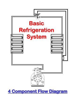
HVACR318 - Refrigeration SPECIAL REFRIGERATION SYSTEM COMPONENTS. THE FOUR BASIC COMPONENTS . Compression systems must have a compressor, condenser, expansion device, and evaporator Other components enhance system operation

E N D
HVACR318 - Refrigeration SPECIAL REFRIGERATION SYSTEM COMPONENTS
THE FOUR BASIC COMPONENTS • Compression systems must have a compressor, condenser, expansion device, and evaporator • Other components enhance system operation • Controls can be electrical, mechanical, or electromechanical devices • Mechanical controls start, stop or modulate fluid flow to increase system effectiveness
TWO-TEMPERATURE CONTROLS • Two-temperature operation is utilized when there are multiple evaporators in the system • These evaporators typically operate at different temperatures • The pressures in these evaporators are therefore different • Two-temperature operation is normally accomplished with mechanical valves
18.4 psig 20°F 18.4 psig 2-temperature device 26.1 psig 30°F
EVAPORATOR PRESSURE CONTROL • Evaporator pressure regulator (EPR) • Prevents the pressure in an evaporator from dropping below a predetermined pressure • Two pressures control the valve • Spring pressure – pushes to close the valve • Evaporator pressure – pushes to open the valve • Evaporator superheat may be high when the EPR is closed
THE EVAPORATOR PRESSURE REGULATOR Spring Vapor to compressor Seat disc Seat Vapor from evaporator Schrader valve
MULTIPLE EVAPORATORS • An EPR is needed in the suction line of each evaporator except the lowest temperature coil • EPR valves are equipped with Schrader valves to read evaporator pressure • Multiple EPRs can be set at different pressures so each evaporator can be maintained at a different temperature
18.4 psig 10 psig (Lowest pressure evaporator) EPR Valves 28 psig
ELECTRIC EVAPORATOR PRESSURE REGULATOR (EEPR) VALVES • Provide more accurate control • Located at the evaporator outlet • Used on single or multiple evaporator systems • Microprocessor senses case discharge air temperature • Designed to maintain discharge air temperature in the refrigerated case • Controlled by a bipolar step motor
CRANKCASE PRESSURE REGULATOR (CPR) • Located close to the compressor • Prevents compressor from overloading on start-up • Provides a limit to the pressure that can enter the compressor • Referred to as a close on rise of outlet (CRO) valve • Resembles an EPR valve
THE CRANKCASE PRESSURE REGULATOR Spring Vapor from evaporator Seat disc Seat Vapor to compressor Schrader valve
18 psig 5 psig Evaporator Crankcase pressure regulator Liquid line
ADJUSTING THE CPR VALVE • Valve is best adjusted under a high load condition • An ammeter should be used when setting the valve • Excessive amperage indicates that too much refrigerant is entering the compressor • Turning the adjusting screw into the valve reduces the refrigerant pressure returning to the compressor • Turning the screw out of the valve increases the refrigerant pressure returning to the compressor
RELIEF VALVES • Release refrigerant from a system when a high-pressure condition exists • Spring-loaded type • Located in the vapor space • Resets after opening • One-time type • Fittings filled with low-temperature solder • Usually located in the suction line near the compressor
SPRING-LOADED RELIEF VALVE SEAL VALVE IN THE CLOSED POSITION
SPRING-LOADED RELIEF VALVE SEAL VALVE IN THE OPEN POSITION
ONE-TIME RELIEF VALVE Hole is filled with a low temperature solder Hole drilled through the relief valve
LOW AMBIENT CONTROLS • Used on refrigeration systems that are operated year round to maintain head pressure • Fan cycling, fan speed control, air volume control, condenser flooding • Intended to simulate design operating conditions • Help to keep the system’s operating pressures within desired ranges
FAN CYLING HEAD PRESSURE CONTROL • Device opens on a drop in head pressure, turning condenser fan off • Device closes on a rise in head pressure, turning condenser fan on • Fan cycling causes large variances in the head pressure • Best used on systems with multiple fans
FAN SPEED CONTROL FOR CONTROLLING PRESSURE • As the outside temperature drops, the fan slows down to reduce the amount of airflow through the condenser coil • As the outside temperature rises, the fan speeds up to increase airflow through the condenser • Some controls monitor the refrigerant’s condensing temperature
AIR VOLUME CONTROL FOR CONTROLLING PRESSURE • Utilizes piston-controlled shutters and/or dampers • As the head pressure drops, the shutters close, reducing airflow through the condenser • Reduced airflow causes the head pressure to rise • During periods of warm ambient temperatures, the dampers are fully open to maximize airflow through the condenser coil
WARM AMBIENT TEMPERATURE Condenser High pressure sensed here Piston Damper blades in the open position Hot gas from compressor
Piston LOW AMBIENT TEMPERATURE Condenser High pressure sensed here Damper blades in the closed position Hot gas from compressor
CONDENSER FLOODING FOR CONTROLLING HEAD PRESSURE • Flooding valves cause liquid refrigerant to move from the receiver to the condenser, reducing its effective surface area, in cold weather • Systems with flooding valves have oversized receivers to hold excess refrigerant charge in warm weather • The valve is closed when outdoor temperature is high (all refrigerant is directed to the condenser)
Condenser flooding valve CONDENSER During warm ambient temperatures, all of the refrigerant is directed to the condenser COMPRESSOR RECEIVER
Condenser flooding valve CONDENSER During low ambient temperatures, the refrigerant is directed to the receiver, bypassing the condenser COMPRESSOR RECEIVER
THE SOLENOID VALVE • Used to start or stop refrigerant flow • Normally open (NO) or normally closed (NC) • Snap-acting valves (open or closed) • Valves must be installed with the arrow pointing in the direction of flow • Often used in conjunction with automatic pump down cycles • Valve position controlled by a solenoid coil
Solenoid coil Solenoid valve body Direction of refrigerant flow
NORMALLY CLOSED VALVE WITH COIL DE-ENERGIZED VALVE IS IN THE CLOSED POSITION
NORMALLY CLOSED VALVE WITH COIL ENERGIZED VALVE IS IN THE OPEN POSITION
NORMALLY OPEN VALVE WITH COIL ENERGIZED VALVE IS IN THE CLOSED POSITION
NORMALLY OPEN VALVE WITH COIL DE-ENERGIZED VALVE IS IN THE OPEN POSITION
PRESSURE SWITCHES • Start and stop current flow to components • Low pressure switch – Closes on a rise in pressure • High pressure switch – Opens on a rise in pressure • Low ambient control – Closes on a rise in pressure • Oil safety switch – Opens on a rise in pressure
LOW-PRESSURE SWITCH • Can be used as low-charge protection and space temperature control • Low-charge protection • Cut-out pressure set well below normal operating pressure • Cut out pressure should be set above atmospheric pressure to prevent atmosphere from being pulled into the system • Prevents system from operating in a vacuum • Control is normally reset automatically
LOW-PRESSURE CONTROL APPLIED AS A THERMOSTAT • Control will cut off the compressor when the pressure equals the system pressure that corresponds to a temperature about 15° cooler than desired box temperature • Control is rated by pressure range and current draw of the contacts
L2 L1 T-stat Overload CONTACTOR Low pressure control MOTOR START RUN
AUTOMATIC PUMP-DOWN SYSTEMS – (SHUTDOWN) SEQUENCE OF OPERATION • Normally closed liquid-line solenoid valve controlled by a thermostat • Thermostat opens when desired box temperature is reached • The solenoid is de-energized and closes • Compressor continues to pump refrigerant • The suction pressure drops • Low-pressure control opens when suction pressure drops • Low-pressure control controls compressor operations
Low pressure control closed L2 L1 L2 L1 Thermostat closed Liquid line solenoid valve open Compressor energized
Low pressure control closed L2 L1 L2 L1 Thermostat open Liquid line solenoid valve closed Compressor energized
Low pressure control open L2 L1 L2 L1 Thermostat open Liquid line solenoid valve closed Compressor de-energized
AUTOMATIC PUMP-DOWN SYSTEMS – (STARTUP) SEQUENCE OF OPERATION • When the box temperature rises, the thermostat closes • The liquid-line solenoid is energized • Refrigerant flows to the evaporator • The compressor is still off • When the low-side pressure increases, the low-pressure control closes • The compressor is once again energized
Low pressure control open L2 L1 L2 L1 Thermostat open Liquid line solenoid valve closed Compressor de-energized
Low pressure control open L2 L1 L2 L1 Thermostat closed Liquid line solenoid valve open Compressor de-energized
Low pressure control closed L2 L1 L2 L1 Thermostat closed Liquid line solenoid valve open Compressor de-energized
Low pressure control closed L2 L1 L2 L1 Thermostat closed Liquid line solenoid valve open Compressor energized
HIGH-PRESSURE CONTROL • Prevents compressor from operating at high head pressures • Control opens on a rise in pressure • Can be automatically or manually reset • Should be set at a pressure higher than the normal operating head pressure • Manual reset controls provide better equipment protection
LOW-AMBIENT FAN CONTROL • Starts and stops the condenser fan motor in response to head pressure • Starts the condenser fan motor when the head pressure rises • This setting should be lower than the set point on the high-pressure control
OIL PRESSURE SAFETY CONTROL • Larger compressors are equipped with oil pumps • Oil pump is connected to the compressor crankshaft • Oil is forced through holes in the crankshaft • Measures net oil pressure • Net oil pressure = pump outlet pressure – suction pressure • Control uses a double bellows • Has a time delay built into the control to allow oil pressure to build up
DEFROST CYCLE (MEDIUM-TEMPERATURE REFRIGERATION • Typical box temperature ranges from 34°F to 45°F • Coil temperatures are normally 10° to 15°F cooler than the box • Coil will be operating below 32°F but box will be above 32°F • Air in box is used to defrost the coil in the off cycle
RANDOM OR OFF-CYCLE DEFROST • Coil defrosts using box temperature air compressor cycles off on the thermostat • Evaporator fan will continue to run while the compressor is off • Air in box defrost coil • Coil defrosts whenever compressor cycles off