Download
1 / 40
410 likes | 824 Vues
CE 370 Sedimentation. Sedimentation. Objectives Uses Sedimentation Basins Types of Settling Sedimentation in Water Treatment

E N D
Sedimentation • Objectives • Uses • Sedimentation Basins • Types of Settling • Sedimentation in Water Treatment • Sedimentation in Wastewater Treatment
Objectives of Sedimentation To separate solids from liquid using the force of gravity. In sedimentation, only suspended solids (SS) are removed.
Uses of Sedimentation • In Water Treatment • In Wastewater Treatment
Water Treatment • Prior to filtration of surface water • Prior to filtration of coagulated-flocculated water • After adding lime and soda ash In softening of water • In iron and manganese removal plants after treating the water
Wastewater Treatment • Removal of SS in primary sedimentation basins • Removal of biological floc in activated sludge processes (final sedimentation basin) • In tertiary treatment • Removal of humus after trickling filters (final sedimentation basins)
Sedimentation Basins • Shapes • Circular • Rectangular • square • Sizes • Circular • 15 to 300 ft (diameter) and 6 to 16 ft (depth) • Typical sizes are 35 to 150 ft (diameter) and 10 to 14 ft (depth) • Square • 35 to 200 ft (width) and 6 to 19 ft (depth) • Freeboard • 1 to 1.25 ft for circular and square tanks
Sedimentation Basins • Sizes • Rectangular ( depends on sludge rake mechanism) • Sprocket and chain-driven rakes • 5 to 20 (width), up to 250 ft (length) and > 6 ft (depth) • Rakes supported from a traveling bridge • 10 to 120 (width) and 40 to 300 (length) • Tandem scrapers • 2 : 1 length-to-width ratio
Types of Settling • Type I settling (free settling) • Type II settling (settling of flocculated particles) • Type III settling (zone or hindered settling) • Type IV settling (compression settling)
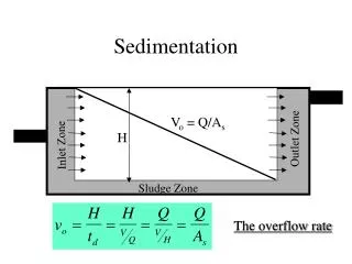
Type I settling (free settling) • Settling of discrete (nonflocculent) particles • Settling of sand particles in grit chamber • Design Parameters • Dimensions [length (L), width (W), and depth (H)] • Volume (Vol) • Settling Velocity (V0) • Horizontal velocity (V) • Detention Time (t) • Flow rate (Q)
Design Equations • Since LW is plan area (Ap), then • V0 = (Q/Ap) = overflow rate or surface loading • This shows that the surface loading is equal to the settling velocity of a particle that is 100% removed • The same equations can be applied to circular tanks. In this case, the horizontal velocity, V is:
Type II settling (settling of flocculated particles) • Particles flocculate during settling • Primary settling of wastewater • Settling of chemically coagulated water and wastewater • A batch settling tests are performed to evaluate the settling characteristics of the suspension
Type III settling (zone or hindered settling) • Is the settling of an intermediate concentration of particles • The particles are close to each other • Interparticle forces hinder settling of neighboring particles • Particles remain in fixed position relative to each other • Mass of particles settle as a zone
Type IV settling (compression settling) • Settling of particles that are of high concentration • Particles touch each other • Settling occurs by compression of the compacting mass • It occurs in the lower depths of final clarifiers of activated sludge
Sedimentation in Water Treatment • Settling characteristics of floc depend on: • Water characteristics • Coagulant used • Degree of flocculation • For water coagulated with alum or iron salts • Overflow Rates • 20.4 to 40.8 m3/d-m2 • Detention Times • 2 to 8 hours
Sedimentation in Water Treatment • In lime-soda softening plants • Overflow Rates • 28.6 to 61.2 m3/d-m2 • Detention Times • 4 to 8 hours
Sedimentation in Wastewater Treatment • Primary sedimentation • To remove settleable solids from raw wastewater • Secondary sedimentation • To remove MLSS in activated sludge process • To remove biological growth sloughing off trickling filters • Tertiary and advanced treatment • Remove coagulated-flocculated SS • Remove chemical precipitates
Primary Sedimentation Overflow Rates and Depths for Primary Clarifiers
Example on Primary Sedimentation A primary clarifier for a municipal wastewater treatment plant is to be designed for an average flow o 7570 m3/d. The peak overflow rate is 89.6 m3/d-m2, average overflow rate is 36.7 m3/d-m2, minimum side water dept is 3 m. The ratio of the peak hourly flow to the average hourly flow is 2.75. Determine: 1. the diameter of the clarifier 2. the depth of the clarifier Solution Using average flow, the required area = (7570 m3/d) / (36.7 m3/d-m2) = 206 m2 Using peak flow, the required area = (7570 m3/d) (2.75) / (89.6 m3/d-m2) = 232 m2 Therefore, the peak flow controls. So, 232 m2 = (/4) D2; D = 17.2 m The depth of the clarifier = 3.0 m
Criteria Used in Design of Secondary Sedimentation Basins Overflow rates, Solids Loadings, and Depths for Secondary Clarifiers
Criteria Used in Design of Secondary Sedimentation Basins Suggested Depths for Final Clarifiers for ASP
Criteria Used in Design of Secondary Sedimentation Basins • Detention Time is 1.0 to 2.5 hours (based on average daily flow) • Overflow rates, solids loadings and depths should control in design of final clarifiers • Basins should be provided with baffles and skimmers to remove floating objects
Example on Final Sedimentation A final clarifier is to be designed for an activated sludge treatment plant. Peak overflow rate = 57.0 m3/d-m2, average overflow rate = 24.4 m3/d-m2, Peak solids loading = 244 kg/d-m2, peak weir loading = 373 m3/d-m, and depth = 3.35 m. The flow to the reactor basin prior to the junction with the recycle line = 11,360 m3/day. The maximum recycled sludge flow is 100% of the influent flow and is constant throughout the day. The MLSS = 3000 mg/l, and the ratio of the peak hourly influent flow to the average hourly flow is 2.50. Determine: 1. the diameter of the tank 2. the depth of the tank
Solution The recycle = (100%)(11,360 m3/day) = 11,360 m3/day Average mixed liquor flow = 11,360 + 11,360 = 22,720 m3/day Peak mixed liquor flow = (2.5)(11,360) + 11,360 = 39, 760 m3/day Area of basin (based on average flow) = (11,360 m3/day) / (24.4 m3/d-m2) = 466 m2 Area of basin (based on peak flow) = (28,400 m3/day) / (57.0 m3/d-m2) = 498 m2 Peak solids flow = (39,760 m3/day)(1000 l/m3)(3000 mg/l)(kg / 106 mg) = 119,280 kg/day Area of solids loading = (119,280 kg/day) / (244 kg/d-m2) = 489 m2 Thus the peak overflow rate controls Since 489 m2 = (/4)(D2) the diameter of the basin, D = 25.2 m From the Table, for a clarifier with D = 25.2 m, the suggested depth of the basin = 3.96 m