Comparative Analysis of Diverter Tile Design Concepts for Thermal and Electromagnetic Loads
110 likes | 224 Vues
This study evaluates various diverter tile design concepts, including baseline designs with crossing T-Bars and various single larger T-Bar configurations, aiming to improve thermal and electromagnetic load performance. Concepts assessed include single larger T-Bars (both split and pinned), three-point rotating supports, and smaller tiles (7.5 vs. 15 degrees). The analysis incorporates thermal stress tests and electromagnetic load scenarios, revealing design strengths and weaknesses. Recommendations emphasize designs offering better thermal load management without compromising electromagnetic load handling.

Comparative Analysis of Diverter Tile Design Concepts for Thermal and Electromagnetic Loads
E N D
Presentation Transcript
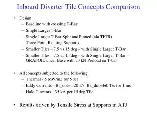
Inboard Diverter Tile Concepts Comparison • Design • Baseline with crossing T-Bars • Single Larger T-Bar • Single Larger T-Bar Split and Pinned (ala TFTR) • Three Point Rotating Supports • Smaller Tiles – 7.5 vs 15 deg – with Single Larger T-Bar • Smaller Tiles – 7.5 vs 15 deg – with Single Larger T-Bar – GRAFOIL under Base with 10 kN Preload on T-bar • All concepts subjected to the following: • Thermal - 5 MW/m2 for 5 sec • Eddy Currents – Br_dot= 520 T/s, Bz_dot=460 T/s for 1 ms • Halo Currents – 35 kA per 15 deg Tile • Results driven by Tensile Stress at Supports in ATJ
Baseline Ibdhs102810/Ibdhs001_struct
Larger T-Bar Ibdhs112410/Ibdhs009_structx
Split and Pinned T-Bar Ibdhs011011/Ibdhs804_struct
Three point pivoting supports Ibdhs010511/Ibdhs703_struct
Pivoting Supports Details Bolt T-Bar Spherical Washers Retaining Clips Not to scale
Smaller 7.5deg Tile Ibdhs120810/Ibdhs101_struct19 Ibdhs120810/Ibdhs101_struct
Grafoil under base of Tile and T-bar T-bar Preloaded to 10 kN Preload only much lower Smaller 7.5deg Tile Ibdhs120810/Ibdhs101_struct21
Summary *Single T-Bar Concepts need to provide radial constraint not explicitly modeled
Conclusions • Baseline with crossing T-Bars • T-slot to small to carry launching force and over turning moments from EM loads. Over constrains tile from thermal load • Single Larger T-Bar • Show improvement over baseline (above) but still over constrains tile from thermal along T-bar axis • Single Larger T-Bar Split and Pinned (ala TFTR) • Attempt to relieve thermal stress along axis – While flexible for thermal, unable to distribute launching load • Three Point Rotating Supports • Allows fairly free thermal expansion. Stress dominated by EM launching forces • Smaller Tiles – 7.5 vs 15 deg – with Single Larger T-Bar • Significant reduction compared to larger tile with Single Larger T-Bar • Gain in thermal stress for smaller tile less than expected due Tile/Tbar relative stiffness • Smaller Tiles – 7.5 vs 15 deg – with Single Larger T-Bar – GRAFOIL under Base with 10 kN Preload on T-bar • Reduces impact of EM loads (ie behaves like preloaded joint) but increases constraint from thermal load
Conclusions • Recommend design that shows better performance for thermal loads, while still performing adequately with EM loads • Thermal loads are more predictable. Better thermal margin may allow for higher heat fluxes if EM loads prove to be less severe • EM loads are less certain and analysis has assumed the worse