BMFB3263 Materials Characterization
BMFB3263 Materials Characterization. Transmission Electron Microscope (TEM). TEM. Topic outcomes. By the end of this topic you should be able to: List down the differences between TEM and SEM Explain basic principle of TEM Explain how bright field and dark field images can be obtained

BMFB3263 Materials Characterization
E N D
Presentation Transcript
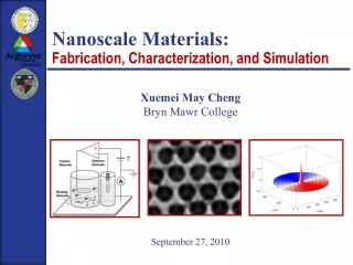
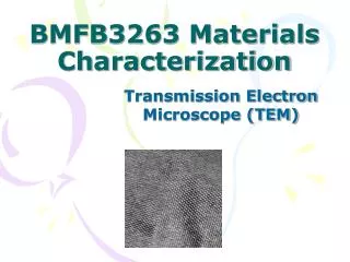
BMFB3263 Materials Characterization Transmission Electron Microscope (TEM)
Topic outcomes By the end of this topic you should be able to: • List down the differences between TEM and SEM • Explain basic principle of TEM • Explain how bright field and dark field images can be obtained • Describe typical sample preparation steps
TEM • The most powerful instruments to investigate the microstructure of materials • TEM enables the fine-scale microstructure to the nanoscale to be examined in sufficiently thin specimens • Why specimen must be sufficiently thin: • To facilitate transmission of a beam of electrons without a great loss of intensity • Maximum transmittable thickness depends on atomic number of the materials • Typical thickness ~250-500 nm • The higher the electron energy, the better transmission the better the transmission through the specimen • Leads to development of TEM with high accelerating voltages 100keV-3MeV
TEM allow observation down to atomic level • TEM capabilities: • Physical and chemical analysis • Micro areas of the specimen
Transmission Electron Microscope (TEM) SEM – image is developed point-by-point, by collecting signal generated by electron interaction as it scan the surface. TEM – image is focused by objective lens while imaging lenses enlarge the final image. SEM gives info on 3-D topography of surface while OM and TEM generate 2-D image of thin, planar slice taken from bulk material. Thickness & diameter of TEM sample is limited. Prepare thin film – mechanical, electrochemical, or ion milling. Coating – sputtering carbon.
Transmission Electron Microscope (TEM) Often equipped with energy-dispersive X-ray spectrometer (EDS) – chemical composition of micro-volume. Cathode, (tungsten filament) heated and high voltage is passed between it and anode emit electrons. Electrons accelerated to anode just below cathode. Some passed thru a tiny hole in anode, & form electron beam. Electro-magnets, placed at intervals down the column, focus the electrons mimicking glass lenses on light microscope.
electron gun – produce stream of monochromatic electrons. • condenser lenses – focus into small, thin & coherent beam. • condenser aperture – eliminate high angle electrons. • transmitted beam is focused by objective lens into image.
Transmission Electron Microscope (TEM) Objective aperture – enhance contrast by blocking out high angle diffracted electrons. Selected area aperture – user to examine periodic diffraction of electrons by ordered arrangement of atoms in sample. Intermediate lens – control magnification. Projector lens – forms a real image on fluorescent screen. Combined both – enlarge image. Image strikes phosphor image screen & light is generated. Darker areas represent thicker or denser areas, & lighter areas for thinner.
Alumina nano-particles Bamboo fibres cells – higher magnification and resolution compared to SEM, lamellation of the cell wall is clear.
Tungsten sulfide nanotube GaN grown on sapphire substrate showing distribution of dislocation at grain boundaries. Arrows show nanotubes present.
Epoxy matrix reinforced by glass-fibre and fumed nano-silica – polymer material has relatively high CTE, silica is added to reduce CTE (silica has low CTE) while glass-fibre to increase stiffness.
HRTEM micrograph of Single-walled Carbon nanotubes produced by CVD growth process. TEM able to get lower resolution, down to 0.2 nm, even a few angstrom (10-10 m) – very useful tool to study nanomaterials, or details in near atomic levels (e.g dislocation, fine precipitate, etc).
Transmission Electron Microscope (TEM) Since material must be exposed to high vacuum, it must be dried. Limited penetrating power of electrons specimens must be sliced into 50 – 100 nm thickness. Contrast in TEM depends on atomic number of atoms in specimen ; the higher the atomic number, more electrons are scattered and the greater the contrast. Biological material composed of very low atomic number atoms (C, H, N, P & S). Thin sections can be made visible by selective staining.
Main features of conventional TEM similar with SEM • Major parts • Evacuated column contains electron source usually tungsten filament or LaB6 crystal, • Assembly of condenser, objective and projector lenses • For high and ultra-high resolutions, <0.5nm field emission or extended Schottky emission cathodes are preferred. • Current TEM design • Provide clean and high vacuum system • Use ions pumps to minimise specimen contamination
From Figure- five-lens illumination system • Trend to increase number of lenses • To optimise the overall performance of the instrument • Maximise flexibility and ease of operation • Smaller value of reduces effective electron source size and increases the coherence length of the beam • Increase the contrast and resolution of the images and diffraction patterns • When passing through a thin foil specimen, electrons enter the objectives lens whose design and aberrations critically affect the performance of the microscope
Parallel incident electron beam • Diffracted beams leaving the specimen are focused in the back focal plane of the objective lens • The diffraction pattern is imaged if the back focal plane is projected on the viewing screen by reducing the excitation of the first projector lens • Interchangeable objectives apertures typically 50 to 200 m diameter, are positioned close to the back focal plane of the objective lens to enhance image contrast • If an objective aperture intercepts all the diffracted beams and allows only the direct beam to pass • Deficiency contrast occurs and bright field image is formed • Objective aperture can be used to select a single diffracted beam to produce dark field image • Tilt the incident electron beam, the astigmatism of the image is reduced
Comparison of the ray diagram and mathematical description of the image formation process
Ray diagrams in a TEM for diffraction conditions where the back focal plane of the objective lens and screen are conjugate
Bright field imaging where the objective aperture is positioned to allow the direct beam to form the final image Typical bright field image of interphase VC carbide precipitation in low alloy ½%Cr ½%Mo ¼%V steel
Dark field image showing distribution of interphase carbide precipitates Dark field imaging where the illumination is tilted to select a given diffracted beam
Transmission Electron Microscope (TEM) Works much like a slide projector. Projector shines a beam of light through slide, as light passes through it affected by the structures and objects of slide. TEM – shines beam of electron through specimens. Reveals more information of internal structure. Resolving power is approximately three orders of magnitude (10,000) greater than that of light microscope. Short wavelength of electron – easy to obtain resolution of 3 nm. Samples limited to less than 3 mm diameter & 100 µm thick. Thickness is critical aspect.
(a) Replica showing faulted substructure within 1 plate of an age Cu-40%Zn alloy, (b) carbides extracted from 1%Cr-1/2%Mo steel
Sample preparation • Electrothinning • Ultra-microtomy • Chemical thinning • Cleavage • Solvent casting • Ion bombardment • Focus Ion Beam (FIB)
Biological samples • e.g. wood and bone • Use ultra-microtomy • Amorphous polymer • Cut into ultramicrotome with a glass or diamond knife if temperature reduced below Tg • Crystalline polymers • Difficult to prepare • Improve cutting properties by chemical staining • Other polymeric materials • Dissolve in solvent and cast on a glass slides • When solvent evaporated, the produced film is coated with thin layer of carbon • Specimen can be melted and re-crystallised before stripping from the glass slide in water
Foils e.g. silica, germanium and magnesium oxide • Chemical etching technique • Hard to produce foils with large and uniform thin areas • Ceramics and semiconducting materials • Use ion bombardment to thin the specimen- surface of material is bombarded with ions of an inert gas, Ar • Ion bombardment can be used for oxides, carbides, nitrides, ceramics, glasses, metals
FIB • The major development in TEM’s sample preparation • FIB can be used to machine specimens from all types of material • Fast (less than 2 hours per foil), precise