Priority encoder
Priority encoder. Overview. Priority encoder- theoretic view Other implementations The chosen implementation- simulations Calculations and comparisons. The target of the project. Building priority encoder using the multilevel lookahead and folding techniques. Uses of priority encoding.


Priority encoder
E N D
Presentation Transcript
Overview • Priority encoder- theoretic view • Other implementations • The chosen implementation- simulations • Calculations and comparisons
The target of the project Building priority encoder using the multilevel lookahead and folding techniques
Uses of priority encoding • INR - interconnection network router • design of SAE – sequential address encoder of a content associate memory (CAM) • microcontroller and microprocessor (incrementer / decrementer)
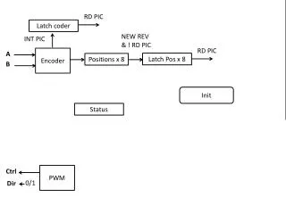
basic concepts of priority encoders The i-th output bit EPi =Di * Pi Di- the input data Pi- thepriority token passed into this bit the relationship between Pi and Pi-1 Pi = Di-1 * Pi-1 the generated EPi is EPi = Di * Di-1 * Di-2 … D1 * D0
Different implementations For 4 bit priority encoder
matrix Sum of minterms, the straight-forward implementation Because of a minimal distance needed between the lines the layout is large and complicated.
Basic units The structure is build from equal units. Each unit calculates yi and xpi for the i-th bit
Then, by chaining the units we construct the output In this implementation we save silicon area, but pay in propagation delay
tree Tree of multiplexers implemented by butterflies Efficient implementation in area and power, has longer propagation then the folding technique
the multilevel lookahead structure The output third-level lookahead signal of the ith 8-bit macro is: LA3i|i=0~n-1 = D8i+7 + D8i+6 + D8i+5 + D8i+4 + D8i+3 + D8i+2 + D8i+1 + D8i + LA3i-1 LA3-1 = 0 n = N/8 N – number of input bits The ith 4-bit sub macros LA2i = D8i+3+D8i+2+D8i+1+D8i+LA3i-1
The 8-bit macro formulas EP8i = D8i * LA3i-1 EP8i+1 = D8i+1 * D8i * LA3i-1 EP8i+2 = D8i+2 * D8i+1 * D8i * LA3i-1 EP8i+3 = D8i+3 * D8i+2 * D8i+1 * D8i * LA3i-1 EP8i+4 = D8i+4 * LA2i EP8i+5 = D8i+5 * D8i+4 * LA2i EP8i+6 = D8i+6 * D8i+5 * D8i+4 * LA2i EP8i+7 = D8i+7 * D8i+6 * D8i+5 * D8i+4 * LA2i
The folding technique-first level folding • The LA3i that generated by the macro with the higher priority can be connected to other macros with lower priority. • Such connection canmake the critical path shorter • In this connection we’ll lose the advantage in layout arrangement and wiring complexity
Folding - implementation • We’ll connect LA30 to the second and the fourth macros (not to the third) and we’ll get 2x2 matrix • in this way the fourth macro is connected to 2 neighboring macros • the number of gate delays is reduced to 4 (<log232 )
Multilevel folding • In order to reduce the gate delay to be less then log2N in grater priority encoders, we can apply the folding technique again & again for example : N=128 • First-Level folding : 8 gate delay • Second-Level folding : 7 gate delay • Third-Level folding :<7 gate delay
For 256-bit priority encoder the new design can achieve about 10 times performance while spending ½ power consumption.
The implementation We decided to implement the project using bottom up architecture, starting with a 1 bit unit. Each stage will be checked separately. Moving to the next stage is only after the previous stage is finished
1 bit unit At first we implemented 1 bit unit and checked it. The circuit:
The output The simulation: Lookahead bit The input The clock
The 4 – bit unit The 4 bit unit circuit:
The outputs: Lookahead When the lookahead high all the outputs equals zero outputs
The output signals v3 Not valid v0
The next lookahead v7 v4
The problem we encountered “glitches”
The “glitch” the glitch starts after clock rising clock rising
The widest glitch comes at higher bits clock Bit #60
Propagation delay - reduction To minimize the propagation delay of the EP we made the following changes : • Reduced the clock period from 200ns to 20ns. • Divide the clock pulse to different periods for low time and high time. Those changes made under the constrains of : • Keeping the high pulse length 80% of the base pulse. • Making sure all the requested changes and currents are stable before clock raising. • The optimum result we conclude for the clock period: 5ns for low time and 15ns high time.
The vhdl simulation of a 32 bit priority encoder Here the lsb of input changes from 0 to 1, and the output changes