Download
1 / 69
700 likes | 881 Vues
(Sub)millimeter Astronomy with Single-Dish Telescopes – Now and in the Future. Karl M. Menten (Max-Planck-Institut für Radioastronomie). Submillimeter Astronomy – Major science drivers: The cosmological submm background – the star formation history of the universe at high z

E N D
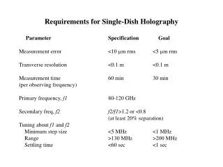
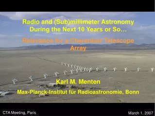
(Sub)millimeter Astronomy with Single-Dish Telescopes – Now and in the Future Karl M. Menten (Max-Planck-Institut für Radioastronomie)
Submillimeter Astronomy – Major science drivers: • The cosmological submm background – the star formation history of the universe at high z • Structure and energetics of molecular clouds • Star and planetary system formation • Astrochemistry • the Solar System
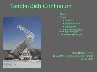
Single dish vs. interferometer? • Basic facts: • (If you can calibrate your phases) an interferometer is much better to detect faint (point-like) sources • Single dish observations are necessary to provide short- spacing information • Bolometer arrays will become very large (thousands of elements) • Many dozen times the collecting area of ALMA and, thus, very much faster if noise not dominated by systematics (atmosphere) and if the confusion limit is not reached • Heterodyne arrays will have ~100 elements at 3 and 2 mm and dozens at submm wavelengths
Advantages of array receivers: • Mapping speed • Mapping homogeneity (map lage areas with similar weather conditions/elevation) minimize calibration uncertainties.
Pierce-Price et al. 2000 Bolometer arrays have completely dominated the field of submillimeter continuum observations for ~20 years now The power of (bolometer) array science: The Galactic Center Region as seen by SCUBA at 850 m Talks by: Borys, Glenn, Greaves, Johnstone, Kauffmann Posters by: Aguirre, Carpenter, Dowell, Li, Sutzki, et al.
The sub-mm Extragalactic Background resolved: Hughes et al. 1998
SCUBA LABOCA SCUBA-2 37 bolometers 295 bolometers ~5120 bolometers Bolometer arrays are getting ever larger: yesterday very soon 2006? In addition: MAMBO-II, Bolocam, SHARC-II, …
12' > 300 higher mapping speed SCUBA-2 12' The HDF-North SCUBA Super-map 850 m • 12’ x 12’ (14“ FWHM) • rms 1 – 4 mJy • 16 sources > 4 • 15 sources between 3.5 and < 4 • at 450 m: 5 sources > 4 Obviously still far from confusion limit
Voss et al. 2005 Cumulative Number Counts [deg-2] Confusion limit ist ~0.7 mJy (3) at 850 m. To cover 1 square degree with 5120 bolometers with 100 mJy s-1/2 takes ~40 hours.
ALMA will be crucial to get positions accurate enough for optical spectroscopy ( redshifts), maybe even determine redshifts on its own. Accurate position determinations via VLA are currently a bottleneck, as each source requires many hours of observing time. … and no VLA for the southern hemisphere. Spitzer positions might save the day!
Fundamental innovations in bolometer technology/observing • Superconducting bolometers • Superconducting TES (Transition Edge Sensors) thermistors • SQUID multiplexer integrated with the bolometers on the wafer • SQUID readout amplifier • Much reduced complexity, greater sensitivity • Much larger bolometers possible
Fundamental innovations in bolometer technology/observing • “Fast scanning” (= no chopping) • Made possible by changes in read-out electronics (DC- biased/AC- coupled AC-biased/DC-coupled) • DC-coupled electronics allow much faster scanning (scanning speed was limited by 2 Hz chopper frequency) • No chopper means • faithful imaging of large structures • free choice of scan direction • less complexity • new observing modes • Technique successfully used at SHARC-II/CSO
Bolometer array sizes will ultimately (= soon) be limited by the field of view of the telescope. • SCUBA–II will completely fill its. • Possible solutions: • Telescopes dedicated to large RX array operation? • e.g. off-axis antenna/modified Gregorian design (South Pole Telescope; see http://astro.uchicago.edu/cara/research/decadal/decadal-submm.pdf • (p. 33 ff) • Radically new, different optics designs possible?
The LSST, a telescope designed for a 3° field 8.4 m diameter f/1.25 Cryostat window diameter: 1.28 m Not feasible for radio astronomy huge sidelobes cryostat http://www.lsst.org/lsst_home.shtml
APEX Cassegrain optics N. Halverson/E. Kreysa
Heterodyne arrays are becoming available just now: HERA = HEterodyne Receiver Array
Common sense requirements: Schuster et al. 2004 http://iram.fr/IRAMES/telescope/HERA/ • Important: • Uniform beams • Uniform TRX • and • TRX not “much” worse than TRX of state-of-the-art single pixel RX
Columbia/CfA 1m CO J = 1 0 (115 GHz)FWHM = 8.7 arcmin FWHMeff= 30 arcmin IRAM 30m CO J = 2 1 (231 GHz)HERA 9 x 11” Factor ~160 in resolution! Ungerechts & Thaddeus 1987 Schuster et al. 2004
JCMT Heterodyne Array Receiver Programme • 16 elements • 325 – 375 GHz • 14" FWHM http://www.mrao.cam.ac.uk/projects/harp/
Philipp et al. 2005 CHAMP+ Carbon Heterodyne Array of the MPIfR • 7 pixels • frequency range 602 – 720 and 790 – 950 simultaneously • beamsize 9" – 7" and 7" – 6" • IF band 4 – 8 GHz http://www.mpifr-bonn.mpg.de/div/mm/tech/het.html#champ http://www.strw.leidenuniv.nl/~champ+/
Common sense requirements for any array RX: • Important: • Uniform beams • Uniform TRX • and • TRX not “much” worse than TRX of state-of-the-art single pixel RX All of the above superbly met by MMIC array spectrographs!
focal plane array: 4×4 pattern. • currently mounted on the FCRAO 14m telescope • Will be moved to the LMT • fixed tuning => best performance at all frequencies • being expanded to 32 elements • InP MMIC pre-amplifiers: 35-40 dB gain band • (Tsys=50 – 80 K) • instantaneous bandwidth: 15 GHz (85 – 115.6 GHz withonlytwo local oscillator settings) http://www.astro.umass.edu/~fcrao/instrumentation/sequoia/seq.html
W-band (80 – 116 GHz) Science with MMIC Array Spectrographs (MASs) Apart from CO J=1-0 lines there are ground- or near-ground-state transitions of HCN, HNC, CN, N2H+, HCO+, CH3OH, SiO… all between 80 and 115 GHz Because of their high dipole moments, these species trace high density gas, n > 104 cm-3( CO: n > 102 cm-3) Large-scale distribution of these molecules on larger GMC scales poorly known Strong emission in these lines, as well as in rare C18O isotope, traces high column densities ( star formation) These lines are very widespread (= everywhere) over the whole Galactic center region (-0.50 < l< 20)
Other most interestingprojects include complete (mostly) 12CO and 13CO mapping of nearby galaxies. These are HUGE (many square arc minutes)! Such maps would be interesting in their own right and areabsolutely necessaryas zero spacing information for CARMA, the PdBI, and ALMA. REALLY FANTASTICwould be MASs on CARMA and the PdBI!!! … and they would make these facilities highly competitive in the ALMA era, as ALMA will (probably) not have MASs for a very long time.
Sensitivity const 1 for 8/10 bit sampling FFT spectrometers! With the IRAM 30m telescope at 90 GHz it would take 25/N hours to produce a Nyquist-sampled map of area one square degree with an N element MAS at an rms noise level of 0.2 K and a velocity resolution of 1 km/s.
All on one chip: FPGA (= Field Programmable Gate Array) New Backend Option: Fast Fourier-Transform (FFT)-Spectrometers Principle: • Direct sampling of RX IF with 8/10 bit resolution • Continuous FFT calculation with given window function (to suppress side lobes) • Calculation of power spectrum • Power spectrum averaging
Overwhelming advantages of FFT Spectrometers: • FPGAs: Field-Programmable Gate Arrays • ADC with 8 or 10 bit sampling (ACs: 2bit) • higher sensitivity, no need for total power detectors • Much higher dynamic range Leveling much simpler simplification of IF module • 100% mass production chips no custom made chips much better reacion to markets take full advantage of Moore’s law • very high channel numbers: • Today: 1 GHz/32768 channels • Soon (1 – 2 yrs): 2 GHz/65536 channels • Very high degree of integration: Integration of a complete spectrometer(digital filters, windows, FFT, power builder and accumulator) of one chip (AC’s use cascaded chips • can be re-programmed • much lower power consumption (more reliable) B. Klein
DRAO/ROE/DAO/NRAO Data reduction machine FFTS data reduction “machine” Correlators IF racks http://www.acquiris.com/ http://www.drao-ofr.hia-iha.nrc-cnrc.gc.ca/science/jcmt_correlator/ FFTS 32 x 0.8 GHz (32 x 1024 channels) = 1 MHz v = 1km/s@300 GHz 40 x 1 GHz (40 x 32768 channels) = 30 kHz v = 0.03km/s@300 GHz
SEQUOIA is just the beginning: MMIC Array Spectrographs (MASs)will • soon (within a few years) have ~100 elements and • somewhat later have many 100s of elements • Large MMIC FPAs currently being developed at JPL (PI Todd Gaier) driven by cosmology (T. Readhead)/space • (FFTS) backends will be available • With LOs integrated, MASs will revolutionize large areas of molecular line astronomy • Question: Will HEMTs become competitive at shorter λλ?
Mapping speed and sensitivity estimates indicate that very large sections (if not all) of the Galactic plane can be imaged • HUGE advantage over SiS arrays:Manylines in HEMT band can be imagedsimultaneously • Necessary Spectrometer capability: • Example W-Band: • Want to do 20 lines simultaneously • need ~300 km/s (= 100 MHz) each • Need N 20 100 MHz = N 2 GHz 2 GHz FFTS bandwidth cost ~ 40 kEU today/MUCH less next year At today’s prizes, an FFTS for a 100 element array would cost 4 MEU HOWEVER:Above is the de luxe correlator. To save money, could do fewer lines, use narrower bandwidths Also: Remember Moore’s Law!!! Actually, FFTS prizes are falling hyper-Moore these days Expect 3 kEU/GHz very soon
The same spectrometer serving a multi-element MAS would also allow very wide band spectral line surveys toward single positions
IRAM 30m telescope Sgr B2-N “Large Molecule Heimat” 10 minutes per spectrum (near) confusion limit (Belloche, Comito, Hieret, Leurini, Menten, Müller, Schilke) 3 mm region (70 – 116 GHz) in 500 MHz chunks 4000 – 5000 lines!!!! With a HEMT RX this would have taken 2 LO settings Factor ~100 savings in observing time
FFT-Spectrometers – Timeline and Perspectives: • 2005/MPIfR:Development of an FFT Spectrometer with • 16384 channels • 500 MHz bandwidth • SUCCESS:Brought into operation at the 100m telescope (April 2005) and (1GHz/32768channels) at APEX (June 2005)! FFTS Technology available today!
FFT Timeline – Perspectives (cont'd): 2005 – 2009: Doable today(!): • 3 GHz BW using three cascaded ADCs @ 2GS/s (10- bit) and • analog input BW of ~3.3 GHz • FFT-Processing: continuous 4 GS/s with 64.000 channels inone high-end Xilinx-Chip (XILINX VII Pro70) (Study by RF-Engines). • Cost: kEU 15 – 20 for 1 GHz BW (Hardware) • ca. 90 kEUR (one time only) for Xilinx-programming • Firm RF-Engines: http://www.rfel.com/Newseventsdetail.asp?ID=68
Timeline – Perspectives (cont'd): > 2009: • Complexityof Xilinx chips doubles every 14 – 18 months • ► Costs: • Grow linearly with each RX element • Minimal serial production costs by simple reproduction of system
FFTSs and MASs Synergy – Pooling resources FFTSs: Bernd Klein, MPIfR, bklein@mpifr-bonn.mpg.de Collaboration with Arnold Benz (ETH Zürich/Acqiris) Potential “users” for FFTSsandMASs (= possible co-financers): • IRAM • APEX • LMT • Effelsberg 100m telescope • GBT • Madrid 40m telescope, Sardinia Telescope + ...
Submillimeter Facilities in the high Atacama desert: • ASTE – The Atacama Submillimeter Telescope Experiment • 10m • NAO Japan, Tokyo U., Osaka Prefecture U., U. Chile • http://www.alma.nrao.edu/library/alma99/abstracts/sekimoto/sekimoto.pdf • Talk by H. Ezawa (next) • Nanten-2 • 4m • Nagoya U., Osaka Prefecture U., Seoul National U., Cologne U., Bonn U., U. Chile • http://scorpius.phys.nagoya-u.ac.jp/workshop/kawai/NANTEN-2.html • http://www.ph1.uni-koeln.de/workgroups/astro_instrumentation/nanten2/ • APEX – The Atacama Pathfinder Experiment
The APEX telescope • Built and operated by • Max-Planck-Institut fur Radioastronomie • Onsala Space Observatory • European Southern Observatory • on • Llano de Chajnantor (Chile) • Longitude: 67° 45’ 33.2” W • Latitude: 23° 00’ 20.7” S • Altitude: 5098.0 m • 12 m • = 200 m – 2 mm • 15 m rms surface accuracy • currently (June 2005) in final testing phase • First facility instruments: • 345 GHz heterodyne RX • 295 element 870 m Large Apex Bolo- meter Camera (LABOCA) • http://www.mpifr-bonn.mpg.de/div/mm/apex/
First light instruments: in operation now (June 2005) Instrumentation Bolometers • LABOCA-1: 295-channel at 870 µm (MPIfR, Bochum U., IPHT Jena) • FOV: 11', beam 18” (same as MSX and Herschel 250µm) • 37+-channel at 350 µm (MPIfR) • 324-channel at 1.4/2 mm for Sunyaev-Zel'dovich survey (UCB, MPIfR) • new software: BoA (Python/F95) www.openboa.de • Heterodyne • 183 GHz water vapour radiometer • 210-270 GHz (OSO) • 270-375 GHz (OSO) • 375-500 GHz (OSO) • 460/810 GHz dual channel First Light Apex Submillimeter Heterdyne Rx (FLASH) • 800-900 GHz (MPIfR/SRON, PI) • CHAMP+ 600-720/790-920 GHz, 2×7-elements (MPIfR, PI) • FIR receivers: up to 1.5 THz = 200 micron (OSO, Köln)
Two Major Apex projects: • APEX-SZ • A 870 m Survey of the Galactic plane Concrete projects (Start: Late 2005) Concept
The Sunyaev-Zel'dovich Effect today Big Bang 0 time 14 Gyr 379,000 yr z=1089 Zhang, Pen, Wang 2002
SZ differential surface brightness is independent of redshift. SZ X Carlstrom et al. APEX beam at 2mm (40") ~ BIMA beam at 1 cm
1.4fλ horns coupled array 330 bolo’s in 6 wedges Each TES bolometer coupled through resonant circuit to SQUID readout direct path to Multiplexing 150 GHz and 217 GHz by swapping horns & filters UCB/APEX SZ Array http://bolo.berkeley.edu/apexsz/ 14 cm
DT +150 +100 +50 0 -50 -100 -150 SZ plus CMB SZ Effect APEX 1 deg Simulations by M. White
The APEX Sunyaev-Zel'dovich Galaxy Cluster Survey Basu Beelen Bertoldi/Co-PI Kreysa Menten Muders Schilke Cho Dobbs Halverson Holzapfel Kermish Kneissl Lanting Lee/Co-PI Lueker Mehl Plagge Richards Schwan Spieler White Sunyaev Böhringer Horellou a collaboration between MPIfR and U.C. Berkeley in association with RAIUB, MPE, MPA, OSO, … Discover and catalog several 1000 galaxy clusters in a mass limited survey: map 200 deg2 to ~10 mK rms per ~60" pixel. Constrain cosmological parameters and dark energy equation of state, w. SZ contribution of z>10 Supernova-remnants. Observe evolution of structure, and test theories of structure formation. Study clusters in detail: structure, evolution, galaxy populations. Study CMB secondary anisotropies, weak lensing, Ostriker-Vishniac effect, quadratic Doppler effect, etc. Zhang, Pen, Wang 2002
A Galactic Plane surveywith APEX F. Schuller,K. M. Menten, P. Schilke, F. Wyrowski Max Planck Institut für Radioastronomie
~1 sec of observing time The APEX GalacticPlane surveySurvey definition Sensitivity: reach1 Msunin nearby regions, and a few10 Msunin Galactic Center Gas mass in cores using Hildebrand (1983) and standard physical parameters, b=2, Td=50 K:
The APEX GalacticPlane survey • Main goals: • To have a complete census of high mass star formation in the Galaxy • To derive the protostellar IMF down to below 1 Msol in a number of nearby regions • Proposed area to observe at 870 mm: • -80° < l < +20° ; | b | < 1° • Northern part of the plane: complementarity with SCUBA-2
The APEX GalacticPlane survey • Sensitivity: one-s = 10 mJy • 0.4 Msundetected at 5s at 1 kpc • 30 Msundetected at 5s in the Gal. Center • Some limited areas in a few southern star forming regions with higher sensitivity (well below 1 Msol) • Total observing time: about 1000 hours
The APEX GalacticPlane survey • Instrumentation: LABOCA (Large APEX BOlometer CAmera) = 295 bolometers for observing at870 mm • APEX beam at 870 mm: • 18"=MSX pixels = Herschel at250 mm