Supplemental Restraint Systems
Supplemental Restraint Systems. Objectives. Perform Proper SIR system disable procedure. Basic Airbag System Overview. Supplemental Inflatable Restraint System (SIR). What is the purpose of the Supplemental Restraint (SIR) System?

Supplemental Restraint Systems
E N D
Presentation Transcript
Objectives Perform • Proper SIR system disable procedure
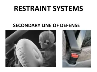
Supplemental Inflatable Restraint System (SIR) What is the purpose of the Supplemental Restraint (SIR) System? SIR system is designed to supplement protection provided by driver and passenger-side seat belts. The air bag is designed to absorb the force produced by a moving occupant during impact. The frontal, side and roof rail airbag systems are considered supplemental restraint systems because they are intended to work in conjunction with the safety belt.
Basic SIR Components of Deployment System What are the basic SIR components? • Driver inflator module • Passenger inflator module • Coil assembly • SDM (Sensing and Diagnostic Module) • Sensors
Driver Inflator Module • Houses air bag and inflator assembly • Located in steering column • Air bag inflates when vehicle is in an accident of sufficient force • Single or dual stage Dual Stage
Passenger Inflator Module • Houses air bag and inflator assembly • Located under the dash pad • Air bag inflates when vehicle is in an accident of sufficient force • Single or dual stage
Hybrid Air Bag • Uses a small explosive charge and a pressurized gas cartridge to cause deployment • The gas cartridge contains inert argon gas pressurized to 3000 psi (20 700 kPa)
Hybrid Air Bag • The igniter is mounted on one end of the pressure tank
Hybrid Air Bag • When energized by the controller, the igniter fires, forcing a plastic bullet through the end of the tank
Hybrid Air Bag • Cool argon gas blows out of the tank to inflate the air bag
Coil Assembly • Allows steering wheel to turn without losing electrical contact between the SDM and driver inflator module • Its connector at the base of the steering column provides wiring to the SDM • Various types
SDM • Microprocessor and controller for the air bag • Primary purpose is to initiate the deployment of a particular air bag module
Sensors • Wide variety • Inputs to the SDM • Determines deployment of the inflator modules
Seatbelt Pretensioner • Designed to “lock-up when a front airbag is deployed • Complete unit must be replaced after activation
PPS What is the purpose of the Passenger Presence System? • Used to detect the weight of a small child or adult on the front outboard seat and is located under the passenger’s seat cushion. • Monitors the passenger seat and automatically helps the SDM determine whether to suppress or allow deployment of the front passenger air bag.
Components of PPS • A sensor mat • A pressure sensor • A seat belt tension sensor • A PPS Module • A PPS Enable-Disable indicator lamp
Sensor Mat • Uses a gel-filled bladder • Located between the seat structure and the foam
Pressure Sensor • Is a transducer clamped to a hose connected to the sensor mat • Translates pressure into a signal that is used by the PPS module to determine weight of occupant
Seat Belt Tension Sensor • Translates seat belt tension into an electronic signal that is used by the PPS module
PPS Module • Provides SDM with input from the pressure sensor • Determines whether there is a small child or adult on the seat and will enable or disable the passenger air bag system
Enable-Disable Lamp • Located on rearview mirror (location may vary) • Indicates the on/off state of the IP module
SRS Tools • Digital Multimeter • Passenger load tool • Removal tool • Tech 2 scan tool
Digital Multi-meter • DMM or DVOM • Isolates specific fault • Before operating the meter, you should readthe entire owner’s manual
SIR Driver/Passenger Load Tool • J 38715-A • Diagnostic aid and safety device • Prevents inadvertent inflator module deployment
Driver Air Bag Removal Tool • J 44298 • Removes the inflator module from the steering wheel • Standard tools (i.e. screwdriver) cannot be used for this procedure
Tech 2 Scan Tool • Hand-held diagnostic computer • Guides you step-by-step through many testing procedures • Captures stored DTCs, freeze frame, and records failures
Safety Precautions Has anyone ever been in an accident where an airbag was deployed?
Vehicle Service • The SIR system (airbag) must be disabled prior to ANY steering column/dashboard service • Serious injury/death may occur Fireman Injured by Airbag
Vehicle Service • Airbag wiring can be identified by a YELLOW connector • Some manufacturers (including GM) also wrap the wires in YELLOW sheathing to aid in identification
Vehicle Service • NEVER cut across airbag wires unless you are certain that the system has been disabled
Vehicle Service • Never repair airbag wiring unless it is a factory approved repair (check service information)
“Live” Inflator Module • During service work, an undeployed inflator module that has been removed from the vehicle must receive special care when handling and storing • Follow all published safety guidelines whenever carrying, storing, shipping, or discarding a “live” inflator module • Specific instructions can be found in current service information
“Live” Inflator Module Carrying: • Always have the trim side (bag opening) facing away from your body • Never carry the inflator module by the wires Storing: • Do no expose inflator modules to temperatures above 65°C(150°F)
Electrostatic Discharge • SDM and Side Impact Sensing Module (SISM) are sensitive to Electrostatic (ESD) • Before removing the SDM or SISM from its anti-static package, ground the package to a known good ground on the vehicle • Always touch a known good ground before handling the SDM or SISM
SDM (Sensing & Diagnostic Module) & Sensor Handling • Should be handled carefully to ensure future deployment when necessary • If the sensor or SDM is dropped from a height of greater than 3 feet, replace the component
Airbag Disposal • All inflator modules must be discharged before disposal • Dual stage airbags must be discharged at both circuits to ensure safety • NEVER discharge an inflator module with the bag facing down
Disabling Procedure- Negative Battery Cable Example Vehicle: 2004 Pontiac Montana 1. Turn the steering wheel so that the vehicles wheels are pointing straight ahead. 2. Place the ignition in the OFF position. 3. Disconnect the negative battery cable from the battery. 4. Wait 1 minute before working on the system. *Refer to SI for vehicle specific procedure
Enabling Procedure- Negative Battery Cable Example Vehicle: 2004 Pontiac Montana • Place the ignition in the OFF position. • Connect the negative battery cable to the battery. • Turn the ignition switch to the ON position. The air bag indicator will flash then turn off. • Perform the Diagnostic System Check- Vehicle if the air bag warning indicator does not operate as described. *Refer to SI for vehicle specific procedure
Proper Precautions • Failure to observe the correct procedures could result in deployment, unnecessary repairs, or personal injury • It is necessary to disable the SIR system when performing on or near SIR components • Several ways to disable the SIR system depending on what type of service is being performed • You must check Service Information (Alldata) for the proper procedure.
Airbag Deploy http://video.google.com/videoplay?docid=-5375862246595244084#docid=537686963646486914