Download
1 / 16
160 likes | 185 Vues
Explore the process and instrumentation diagrams, mechanical aspects, and cryodistribution of cryogenic components at CNRS/IN2P3/IPNO, including valve placements, piping lengths, and benefits of heat exchanger placement. Discover how placing components in the valve box simplifies distribution and assembly.

E N D
ESS Spoke Cryomodule Cryogenic distribution CNRS/IN2P3/ IPNO – Paris-Sud University
Contents • Process and Instrumentation Diagrams • Mechanical aspects • Cold box
Cryodistribution: Spoke PID Heliumsupply T.L (19.5 bar, 40K) Helium return T.L (19.0 bar, 50K) Heliumsupply HP (3 bar, 4.5K) Helium Return VLP (~31 mbar) Helium Return LP (1.05 bar) Valve Box Cryogenic Transfer Line (CTL) Pumping line He conditionning line - (1.5bar, 300K) jumper Spoke cryomodule 23/10/2013 ADT 808 LT TT 808 TT 808 TT 808 TT 808 ADT 808 TT 808 TT 808 PT 808 TT 808 TT 808 TT 808 TT 808 TT 808 TT 808 TT 808 TT 808 TT 808 TT 808 TT 808 TT 808 TT 808 PT 808 PT 808 PT 808 TT 808 TT 808 TT 808 TT 808 TT 808 TT 808 RFT 808 RFT 808 TT 808 TT 808 Helium Return Coupleur (1.05bar, 300K)
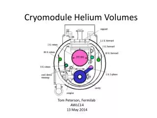
Cryodistribution • Whyplacing the heatexchanger and the cryogenic valves in the cryomodule ?
Cryodistribution: Spoke PID 2 Heliumsupply T.L (19.5 bar, 40K) Helium return T.L (19.0 bar, 50K) Heliumsupply HP (3 bar, 4.5K) Helium Return VLP (~31 mbar) Helium Return LP (1.05 bar) Cold Box Cryogenic Transfer Line (CTL) Pumping line He conditionning line - (1.5bar, 300K) jumper Spoke cryomodule 05/04/2013 (updated 19/11/2013) ADT 808 ADT 808 LT TT 808 TT 808 TT 808 TT 808 TT 808 TT 808 TT 808 PT 808 TT 808 TT 808 TT 808 TT 808 TT 808 TT 808 PT 808 TT 808 TT 808 TT 808 TT 808 TT 808 PT 808 TT 808 TT 808 TT 808 TT 808 TT 808 TT 808 PT 808 PT 808 TT 808 TT 808 TT 808 TT 808 RFT 808 RFT 808 TT 808 TT 808 Helium Return Coupleur (1.05bar, 300K)
Cryodistribution: cryo valves Jumper connection Cool-down valve JT valve Valves are mounted after the cryostating step • Valves are placed at the cryomodule extremities to get access, allowing: • to connect the cryolines (by welding or via fittings); • to achieve leak test.
Cryodistribution Heat exchanger (in the jumper) JT valve Distance fromthis plane (heatexchangerflange) L=2.565 m Cool-down valve L= 1.678 m L= 2.545 m JT
Cryodistribution Fill-in line (from JT valve) – L= 2.620 mm Cool down line – L= 2.480 mm Heat exchanger and valves placed in the valve box
Pipe lengths Heliumsupply T.L (19.5 bar, 40K) Helium return T.L (19.0 bar, 50K) Heliumsupply HP (3 bar, 4.5K) Helium Return VLP (~31 mbar) Helium Return LP (1.05 bar) Valve Box Cryogenic Transfer Line (CTL) L = 1889 mm Pumping line L = 5205 mm L = 2620 mm He conditionning line - (1.5bar, 300K) L = 1291 mm jumper Spoke cryomodule L = 910 mm L = 2565 mm L = 1678 mm ADT 808 LT TT 808 TT 808 TT 808 TT 808 ADT 808 TT 808 TT 808 PT 808 TT 808 TT 808 TT 808 TT 808 TT 808 TT 808 TT 808 TT 808 TT 808 TT 808 TT 808 TT 808 TT 808 TT 808 TT 808 TT 808 PT 808 TT 808 TT 808 PT 808 TT 808 PT 808 RFT 808 RFT 808 TT 808 TT 808 Helium Return Coupleur (1.05bar, 300K)
Pipe lengths Heliumsupply T.L (19.5 bar, 40K) Helium return T.L (19.0 bar, 50K) Heliumsupply HP (3 bar, 4.5K) L = 200 mm ? L = 200 mm ? Helium Return VLP (~31 mbar) Helium Return LP (1.05 bar) Cold Box Cryogenic Transfer Line (CTL) L = 200 mm ? L = 800 mm ? Pumping line L = 4340 mm He conditionning line - (1.5bar, 300K) jumper Spoke cryomodule L = 2680 mm L = 2620 mm ADT 808 ADT 808 LT TT 808 TT 808 TT 808 TT 808 TT 808 PT 808 TT 808 TT 808 PT 808 PT 808 TT 808 TT 808 TT 808 TT 808 PT 808 PT 808 TT 808 TT 808 TT 808 TT 808 TT 808 TT 808 TT 808 TT 808 TT 808 TT 808 TT 808 TT 808 TT 808 TT 808 TT 808 TT 808 TT 808 RFT 808 RFT 808 TT 808 TT 808 Helium Return Coupleur (1.05bar, 300K)
Pipe lengths sum-up • Placing the cryogenic valves and the heat exchanger in the valve box would:
Conclusion • Placing the cryogenic valves and the heat exchanger in the valve box would: • simplify the cryogenic distribution (number of interfaces, number of valves, pipinglengths) (and not onlywithin the cryomodule); • reduce the jumperdiameter; • allow to (leak) test all the cryogenic distribution before cryostating the jumper interface wouldbe the onlyelement to betestedafter cryostating; • ease the cryomodule assembly.
Valve box Interaction with the wave guides Lack of space between valve box and cryomodule
Upgrade of SM18 Infrastructure at CERN P. MaesenDec 2012