Download
1 / 26
270 likes | 375 Vues
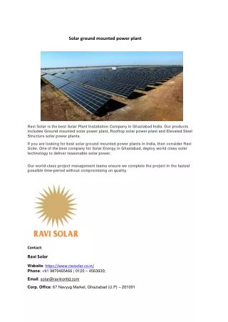
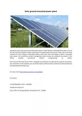
Explore the step-by-step process of installing a 40kW photovoltaic solar power plant, from site surveying to final assembly and connection. Learn about the technology and benefits of photovoltaic solar power generation.

E N D
INSTALLATON OF 40Kw POHOTOVOLTIC SOLAR POWER PLANT Name: Nikesh N. More Roll No. B150087533 College Guide : Dr. N. K. Kamble Company Name: SCILYF Industries PVT LTD. Company Guide: SumitDhage
Content: • Company Profile • Assignment no 1 • Assignment no 2 • Assignment no 3 • Conclusion • Reference
COMPANY PROFILE • Founder Members of SCILYF INDUSTRIES PVT LTD Energy Limited recognize the nations need for energy that is the life line for social and economic progress. • In spite of coming from varied business backgrounds they share a common passion to provide access to clean and affordable energy to industries, commercial establishments and the masses. • we provide reliable and affordable solar energy access and simultaneously provide profitable partnership opportunities to the land owners and other stakeholders. • Capture Solar Energy Limited is an organization focused on providing reliable, affordable electrical Solar Resource based solutions including Solar Thermal and Photovoltaic solutions.
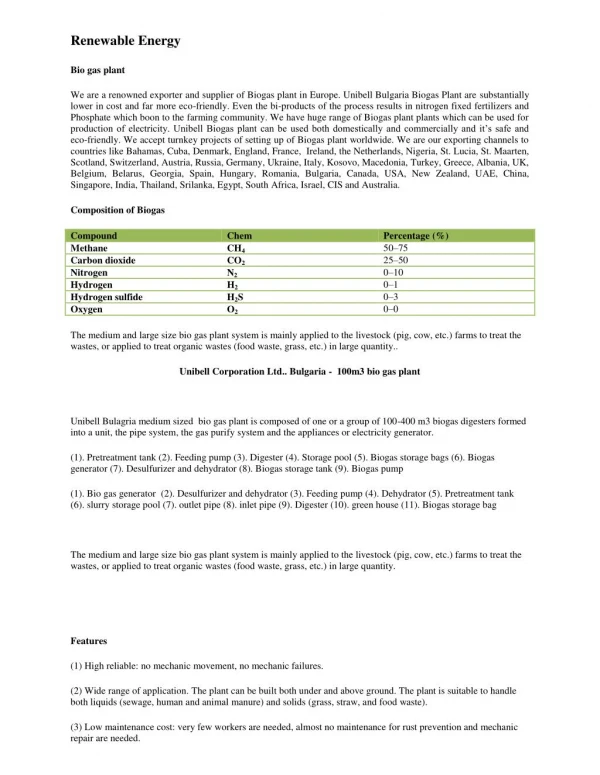
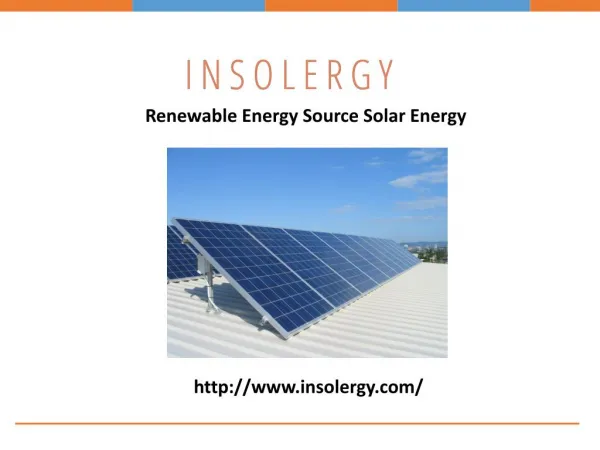
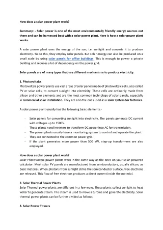
Photovoltaic (PV) Solar Power • Photovoltaic (PV) devices generate electricity directly from sunlight via an electronic process that occurs naturally in certain types of material, called semiconductors. • Electrons in these materials are freed by solar energy and can be induced to travel through an electrical circuit, powering electrical devices or sending electricity to the grid. • Most modern solar cells are made from either crystalline silicon or thin-film semiconductor material. • Silicon cells are more efficient at converting sunlight to electricity, but generally have higher manufacturing costs. • Thin-film materials typically have lower efficiencies, but are simpler and less costly to manufacture
How Solar works? • Solar energy is harnessed and used through a process using photovoltaic cells. These cells or panels are usually made up of two types of silicon. • Sunlight is made up of negative and positive layers, which creates an electrical field. • When the protons hit the surface of the solar cell, the electrons from the light rays are freed, pass to the bottom of the cell and flows through to power appliances. • The flow of electrons is also known as electricity. • To complete the PV module, several layers are added. A - Cover Glass B - Antireflective Coating C - Contact Grid D - N-type Silicon E - P-type Silicon F - Back Contact
Introduction • To fabricate the stands for solar panels. • To solve problems during the installation of solar plant. • Methodology • Fabrication of the stands made of gi. • First the gi bars were cut according to the design using hydraulic saw. • Then all the rods were painted with yellow zinc coating • After drying, the rods are again painted with silver coating. • Then the welding was done using mig. • The next step was positioning of the fixtures. The fixtures were facing south and were inclined at a 18 degrees with the surface. • The final step is to drill the fixture according to the panel size and to join the assembly to the ground using screws.
SITE SURVEYING AND MEASUREMENT • Since the project was new, site surveying was required. • All the important measurements were done. • The length from the top to the bottom of the building was taken for earthing and metering purposes using a measuring tape. • The size of the terrace was also measured for the feasibility purpose. • The direction of the building, terrace and points that can be used for fabrication were also noted.
ASSEMBLY AND INSTALLATION • Of the plant • The final part of the project is assembly. The panels are assembeled to the fixtures using two sided washers. A total of 120 panels of 335w were installed. • The panels are made by Adani solar. • The inverter is made by Solis Pvt. ltd and has a capacity of 40kw. • The panels are connected to dc distribution box and then to the inverter. The inverter is connected to acdb and then to the solar net meter. • The whole assembly is connected with a gi bar which is used for earthing purpose. • There were 3 earthings given to the whole assembly. • Panel earthing- earthing connected to the fixture of the panels. • Inverter earthing- earthing provided to the dcdb. • Lightening arrester- the lightening arrester is a copper rod which conducts electricity in case of lightening and is sent to the earth. • The final process is of earthing. An earth pit is dug and is filled with chemical(bentonite), 3 caps are installed through with 3 rods go in. The rods are connected to the gi strip used for earthing of panel, inverter and the lightening arrester seperately. • The company provides 3 earthings whereas most companies provide only 1 earthing.
CONCLUSIONS • There is 40kw renewable clean energy produced. • Encounter of practical problems and solution to smallest problems. • Better command over fabrication and labour handling. • Increased knowledge in the field of renewable energy using solar.
WHAT IS LIGHTNING? • The clouds get charged during thunder storms and the high potential gradient causes breakdown of insulation of air producing a lightning stroke. • The stroke tries to hit the earth, it is attracted by overhead lines and affects line insulators resulting in flash over or puncture. • The traveling wave reaches to the substation. The insulation of equipment is also stressed. • The device which is used for the protection of the equipment at the substations against travelling waves, such type of device is called lightning arrester or surge diverter. • In other words, lightning arrester diverts the abnormals high voltage to the ground without affecting the continuity of supply. • It is connected between the line and earth, i.e., in parallel with the equipment to be protected at the substation.
Working of Lightning Arrester • When a travelling wave reaches the arrestor, its sparks over at a certain prefixed voltage as shown in the figure below. • The arrestor provides a conducting path to the waves of relatively low impedance between the line and the ground. • The surge impedance of the line restricts the amplitude of current flowing to ground. • The lightning arrester provides a path of low impedance only when the travelling surge reaches the surge diverter, neither before it nor after it. • The insulation of the equipment can be protected if the shape of the voltage and current at the diverter terminal is similar to the shape shown below.
Location of Lightning Arrester • The lightning arrester is located close to the equipment that is to be protected. They are usually connected between phase and ground in an AC system and pole and ground in case of the DC system. In an AC system, separate arrester is provided for each phase. TYPES OF LIGHTNING ARRESTER Rod Gap Horn Gap Explosion Gap or Protective tube Surge Absorber Lightning arrester or Surge Diverters
EARTHING • What is earthing? • The process of earthing is to connect all these parts which could become charged to the general mass of earth, to provide a path for fault currents and to hold the parts as close as possible to earth potential. • In simple theory this will prevent a potential difference between earth and earthed parts, as well as permitting the flow of fault current which will cause the operation of the protective systems
Introduction: Purpose • A typical solar panel converts only 30 to 40 percent of the incident solar irradiation into electrical energy. • Thus, to get a constant output, an automated system is required which should be capable to constantly rotate the solar panel. • The Sun Tracking System (STS) was made as a prototype to solve the problem, mentioned above. • It is completely automatic and keeps the panel in front of sun until that is visible.
Scope • It can be used for small and medium scale power generations. • It can be used for power generation at remote places where power lines are not accessible. • It can be used for domestic and industrial power backup system. Definition • A Solar tracker is an automated solar panel which actually follows the sun to get maximum power. • The primary benefit of a tracking system is to collect solar energy for the longest period of the day, and with the most accurate alignment as the Sun’s position shifts with the seasons. • Dual Axis Tracker have two different degrees through which they use as axis of rotation.
Product Perspective Solar Panel LDRs Arduino UNO Microcontroller Servo Motors
5.Conclusion • The study provides an insight to identify the location and suitable PV technology for large scale deployment of solar photovoltaic system in India. • This information is useful in evaluating the operational benefits of the plant based on the net energy output. • The performance (Capacity utilization factor ) CUF depends on several factors including the solar radiation, temperature, air velocity apart from the module type and quality, angle of tilt(or tracking), design parameters to avoid cable losses and efficiencies of inverters and transformers.
6. Reference 1) Book titled “Solar Energy Principle of Thermal Collection and Storage”, S.P. Sukhatme & J.K.Nayak, McGraw Hill, 2010. ISBN-978-0-07-026064-1. 2) Book titled “Solar Photovoltaic Fundamental, Technologies and Application” Chetan Singh Solanki, PHI Learning, 2011. ISBN-978-81-203-4386-3. 3) Paper titled, “Smart Grid Designs for The Improvement in Solar Technology and its Development”, V.ShirishMurty, ISSN:2278-8948, Vol.2,Jan 2013. 4) Book titled “Non-Conventional Energy Resources”, D.S. Chauhan, S.K. Srivastava, New Age International, 2010. ISBN-978-81-224-1768-5. 5) Paper titled, “Design of a Solar Tracker System for PV Power Plants” Tiberiu Tudorache1, Liviu Kreindler1, 2 Vol. 7, No. 1, 2010