Download
1 / 20
200 likes | 346 Vues
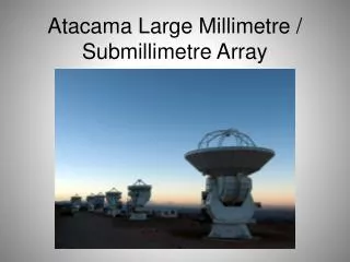
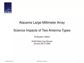
Atacama Large Millimeter Array Science Impacts of Two Antenna Types. Al Wootten, NRAO ALMA Delta Cost Review January 26-27 2006. Antenna Designs in ALMA. Three antenna designs currently in hand: Two will be operated in PSI interferometer in near future:

E N D
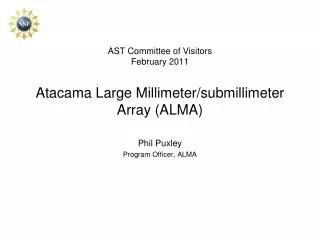
Atacama Large Millimeter ArrayScience Impacts of Two Antenna Types Al Wootten, NRAO ALMA Delta Cost Review January 26-27 2006 ALMA Delta Cost Review
Antenna Designs in ALMA • Three antenna designs currently in hand: • Two will be operated in PSI interferometer in near future: • Vertex (APEX close copy operational at Chajnantor, destiny of this prototype uncertain). • AEC (Basis of AEM design, destiny uncertain). • MElCo prototype disassembled for retrofit to design similar to 3 MElCo production antennas • Four others expected • Production Vertex design (25-32 antennas) • Production AEM design (25-32 antennas) • Production MElCo 12m antennas (3 antennas) • Production MElCo 7m antennas (12 antennas) • For present purposes, only consider production Vertex and AEM designs • As these are evolving, must assume they will be identical to the prototype antennas ALMA Delta Cost Review
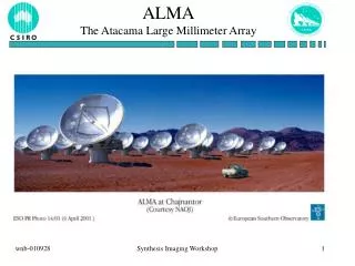
Antennas • Demanding ALMA antenna specifications: • Surface accuracy (25 µm) • Absolute and offset pointing accuracy (2 arcsec absolute, 0.6 arcsec offset) • Fast switching (1.5 deg sky in 1.5 sec) • Path length (15 µm non-repeatable, 20 µm repeatable) • To validate these specifications: two prototype antennas built & evaluated at ATF (VLA) ALMA Delta Cost Review
AEC Prototype Antenna ALMA Delta Cost Review
Vertex Prototype Antenna ALMA Delta Cost Review
VertexRSI and AEC Prototype Antennas ALMA Delta Cost Review
Science Implications • Prototypes accepted from manufacturers • Final technical evaluations complete • Both antennas meet the specifications • What happens with two different antenna "designs" • common mode errors don’t cancel • But differences may help • cost (construction, commissioning, operation) • other ? • Consider: • Surface differences • Pointing • Pathlength • Mosaicking and polarization ALMA Delta Cost Review
Science Implications:The Antenna Surfaces Source: AEG Results Both telescopes easily meet specifications (<25 µm); both are excellent antennas. ALMA Delta Cost Review
Prototype Pointing Results Source: AEG Results Spec: 2” all-sky; 0.6” offset pointing under primary operating conditions ALMA Delta Cost Review
Fast Switching Specification: 1.5 degrees in 1.5 seconds, settling time under 3 seconds. ALMA Delta Cost Review
Path Length Stability • Spec: 15/20 µm repeatable/nonrepeatable *Δt = 3, 10, 30 minutes; **Wind-induced, Δt = 15 minutes ALMA Delta Cost Review
Science Implications • Pointing • Both antennas meet specifications, but the character of pointing differs • in compact configuration • WIND: wind "shadowing“ may have some effect • SUN: sunrise may have some effect • GRAVITY: both designs are essentially rigid • in other configurations • WIND: differs over the site as will the antenna response • SUN & GRAVITY remain constant over the site • Fast Switching • Both antennas meet specifications • Awaiting redesign of AEC quadripod • If not, effect would be to decrease throughput/efficiency ALMA Delta Cost Review
Science Implications • Phase / pathlength / focus • as pointing, but a more subtle effect. • Axis non-intersection may be the dominant effect on pathlength (baseline) prediction, and has no common mode error • Other mechanical deformations would benefit from identical antennas • Gravitational sag, thermal deformation, perhaps other environmental items • Phase effects due to fiber length • Fiber run to antenna is dominant in effective length change (but if monitored and corrected, no common mode) • Polarization matching and primary beam shape • determined by quadripod leg design (shadowing of quadripod legs, but exact shape plays a minor role too) • Lesser effect from the differing arrangement of panels and therefore character of scattering from the edges ALMA Delta Cost Review
Fiber Length • The effective length of the fiber is dominated by the run up the antenna (see ALMA Memo 443). • Differences in the two designs include • Length of fiber run • Degree of thermal shielding • Such variations are monitored and compensated. ALMA Delta Cost Review
Pathlength Effects • Temperature: • Surface RMS changes with ambient temperature from holography: • * VertexRSI: ~0.6-0.7 micron/K. • * AEC: ~0.8 micron/K. • Both deformations had a high degree of structure (like BUS segment print-through for VertexRSI, large-scale 45-degree plus inner-ring print-through for AEC); probably in the noise at highest frequencies, where frequent calibration will be done in any event. • Focal length change due to ambient temperature changes: • * VertexRSI: • 34 micron/C from holography • 36 micron/C from radiometry • * AEC: • 14 micron/C from holography • 20 micron/C from radiometry • All within specification and unlikely to impact science (focus tracked; surface changes small) ALMA Delta Cost Review
Quadripods • The optical path from the sky off the reflector to the subreflector intercepts the quadripod. In both designs, the solid angle subtended by the quadripod is minimized and the point of attachment to the antenna is as close as possible to the edge of the reflector to minimize shadowing. • The shadowing profile is less than 1% of the antenna diameter. • Owing to careful minimization of the quadripod profile, the sidelobes will be small and distant from the primary beam. • Beam profiles were calculated from the shadowing profiles (next slide). • Quadripod shadowing is known for the Vertex design (ALMA Antenna Group Report #40), estimated for the AEC design by Lucas. • Reflections are minimized by profiling of the inward edge of the quadripod legs. • Different lateral motion of the subreflectors with elevation in a homologous antenna could effect cross-polarization; amenable to calculation. • Shadowing is measured using holography and is the same for both antenna designs within a few tenths of a per cent. • Integrated power <1% of that in the main beam, hence sidelobe power will be more than 40 dB below that of the main beam. ALMA Delta Cost Review
Quadripod-dependent Questions Cross Vertex AEC Three sorts of interferometric baselines provide three sorts of beams: Vertex-Vertex, AEC-AEC, and Vertex-AEC. For the most sensitive imaging, these must all be measured and tracked. The most sensitive images include mosaics and polarization images. ALMA Delta Cost Review
Effects of Quadripod Differences • “If one ignores the effects of the sidelobes, it is better to have antennas with different configurations; if you are going to correct for it then it is easier if they are all the same.” –James Lamb • Case One—no correction • The effect of the different sidelobes is small • Since the sidelobes differ, a source won’t be in both at once and the effect on an image is diminished • Interferometric data provide a strong discriminant for sources near the main beam owing to fringe rotation/delay offset • Case Two—correction applied • Worst case is an interfering source in a sidelobe. But with two designs it cannot be in a sidelobe of all antennas at once. One will want to correct for the different antenna patterns ALMA Delta Cost Review
Summary • If quadrupod layout is identical, advantage of a single design exist, but is rather limited • 25 excellent antennas + 25 good antennas is better than 50 good antennas • 50 (or 64) excellent antennas is even better • Each prototype met specifications and qualifies as an excellent antenna • Conclusion: The effect of having two designs for the 12m antennas in ALMA is small. Any imaging effect can be dealt with for the most sensitive images which might need additional care. • Cost probably has a greater effect • 2 designs • 2 software interfaces • 2 Assembly, integration, verification, commissioning and science verification • 3 beams to track in the most sensitive applications ALMA Delta Cost Review
www.alma.info The Atacama Large Millimeter Array (ALMA) is an international astronomy facility. ALMA is a partnership between Europe, North America and Japan, in cooperation with the Republic of Chile. ALMA is funded in North America by the U.S. National Science Foundation (NSF) in cooperation with the National Research Council of Canada (NRC), in Europe by the European Southern Observatory (ESO) and Spain. ALMA construction and operations are led on behalf of North America by the National Radio Astronomy Observatory (NRAO), which is managed by Associated Universities, Inc. (AUI), on behalf of Europe by ESO, and on behalf of Japan by the National Astronomical Observatory of Japan.