EAT 253 STRUCTURAL ANALYSIS I
EAT 253 STRUCTURAL ANALYSIS I. TOPIC 4 DISPLACEMENT METHOD OF ANALYSIS: SLOPE – DEFLECTION EQUATIONS. ILYA BINTI JOOHARI. TOPICS. General procedure Degrees of Freedom Slope – deflection equations General case Fixed – end moments Slope – deflection equations Pin – supported end span

EAT 253 STRUCTURAL ANALYSIS I
E N D
Presentation Transcript
EAT 253STRUCTURAL ANALYSIS I TOPIC 4 DISPLACEMENT METHOD OF ANALYSIS: SLOPE – DEFLECTION EQUATIONS ILYA BINTI JOOHARI
TOPICS • General procedure • Degrees of Freedom • Slope – deflection equations • General case • Fixed – end moments • Slope – deflection equations • Pin – supported end span • Analysis of beams • Analysis of frames: No sidesway • Analysis of frames: Sidesway
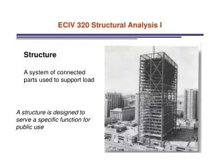
GENERAL PROCEDURE • All structures must satisfy equilibrium, load-displacement, and compatibility of displacements requirements in order to ensure their safety. • There are two different ways to satisfy these requirements when analyzing a statically indeterminate structure. • Force Method • Displacement Method • For the Displacement Method, it first requires satisfying equilibrium equations for the structure. • Once the displacements are obtained, the unknown loads are determined from the compatibility equations using the load-displacement relations.
DEGREES OF FREEDOM • When a structure is loaded, specified points on it, called nodes, will undergo unknown displacements. • Thesedisplacements are referred to as the degrees of freedom for the structure, and in the displacement method of analysis, it is important to specify these degrees of freedom since they become the unknowns when the method is applied.
DEGREES OF FREEDOM • Imagine the structure to consist of a series of members connected to nodes, which are usually located at joints, supports, at the ends of a member, or where the members have a sudden change in cross section. • In two dimensions, each node can have at most two linear displacements and one rotational displacement.
DEGREES OF FREEDOM • Example 1 • Here any load P applied to the beam will cause node A only to rotate (neglecting axial deformation), while node B is completely restricted from moving. • Hence the beam has only one unknown degree of freedom,θAand is therefore indeterminateto the first degree.
DEGREES OF FREEDOM • Example 2 • The beam has nodes at A, B, and C, and so has four degrees of freedom, designated by the rotational displacements,θA,θB and θC,and the vertical displacement ∆A. • It is indeterminate to the fourth degree.
DEGREES OF FREEDOM • Example 3 • If we neglect axial deformation of the members, an arbitrary loading P applied to the frame can cause nodes B and C torotate, and these nodes can be displaced horizontally by an equal amount. • The frame therefore has three degrees of freedom, θB , θC, ∆B, and thus it is indeterminate to the third degree.
GENERAL CASE • In order to develop the general form of the slope –deflection equations, we will consider the typical span AB of a continuous beam which is subjected to the arbitrary loading and has a constant EI.
GENERAL CASE • We wish to relate the beam’s internal end moments MAB and MBA in terms of its three degrees of freedom, namely, its angular displacements, θA and θB, and linear displacement ∆ which could be caused by a relative settlement between the supports. • Since we will be developing a formula, moments and angular displacements will be considered positive when they act clockwise on the span. • The linear displacement ∆ is considered positive, since this displacement causes the cord of the span and the span’s cord angle Ψto rotate clockwise. • The slope-deflection equations can be obtained by using the principle of superposition by considering separately the moments developed at each support due to each of the displacements, θA ,θB and ∆, and then the loads.
FIXED-END MOMENTS • Consider the fixed-supported member shown in Fig. (a), which is subjected to a concentrated load P at its center. • The conjugate beam for this case is shown in Fig. (b). • Since we require the slope at each end to be zero,
FIXED-END MOMENTS • This moment is called a fixed-end moment (FEM). • Note that according to our sign convention, it is negative at node A (counterclockwise) and positive at node B (clockwise). • Assuming these FEMs have been determined for a specific problem (Fig. below), we have
FIXED-END MOMENTS *Inside back cover (Textbook R.C. Hibbeler)
SLOPE – DEFLECTION EQUATION • If the end moments due to each displacement and the loading areadded together, the resultant moments at the ends can be written as Eq. (1)
PIN – SUPPORTED END SPAN • Occasionally an end span of a beam or frame is supported by a pin or roller at its far end. • Whenthis occurs, the moment at the roller or pin must be zero.
PIN – SUPPORTED END SPAN • Here the (FEM)Fis equal to zero since the far end is pinned. Eq. (2)
PROCEDURE FOR ANALYSIS • Degrees of Freedom • By drawing the deflected shape of the structure, it will be possible to identify the number of degrees of freedom. • Slope-Deflection Equations • The slope-deflection equations relate the unknown moments applied to the nodes to the displacements of the nodes for any span of the structure. • If a load exists on the span, compute the FEMs using the table given on the inside back cover. • Equilibrium Equations • Write an equilibrium equation for each unknown degree of freedom for the structure. • If any of the results are negative, they indicate counterclockwiserotation; whereas positive moments and displacements are applied clockwise.
EXAMPLE 1 (EXAMPLE 11.1 - R.C. HIBBELER) • Draw the shear and moment diagrams for the beam shown. EI is constant.
EXAMPLE 1 SOLUTION • Slope-Deflection Equations • Two spans must be considered in this problem. • There is no span having the far end pinned or roller supported. • (FEM)AB = (FEM)BA= 0 since there is no load on span AB.
EXAMPLE 1 • There are four unknown internal moments. • Only the slope at B, is unknown. • Since A and C are fixed supports, θA = θC= 0. • Also, since the supports do not settle, nor are they displaced up or down, ΨAB= ΨBC= 0.
EXAMPLE 1 • Span AB • Span BC Eq. (1)
EXAMPLE 1 • Equilibrium Equations • The four equations contain five unknowns. • The necessary fifth equation comes from the condition of moment equilibrium at support B.
EXAMPLE 1 The free-body diagram of the entire beam and the shear and moment diagrams:
EXAMPLE 2 (EXAMPLE 11.2 - R.C. HIBBELER) • Draw the shear and moment diagrams for the beam shown. EI is constant.
EXAMPLE 2 SOLUTION • Slope-Deflection Equations • Two spans must be considered in this problem.
EXAMPLE 2 • Since the supports do not settle, ΨAB= ΨBC= 0. • θA= 0 • Span AB Eq. (1)
EXAMPLE 2 • Span BC Eq. (2)
EXAMPLE 2 • Equilibrium Equations • The above three equations contain four unknowns. • The necessary fourth equation comes from the conditions of equilibrium at the support B.
EXAMPLE 2 The free-body diagram of the entire beam and the shear and moment diagrams:
EXAMPLE 3 (EXAMPLE 11.3 - R.C. HIBBELER) • Determine the moment at A and B for the beam shown.The support at B is displaced (settles) 80 mm. • E = 200 GPa
EXAMPLE 3 SOLUTION • Slope-Deflection Equations • Only consider one span (AB) • Since there is no loading on span AB, theFEMs are zero • The downward displacement (settlement) of B causes the cord for span AB to rotate clockwise.
EXAMPLE 3 • The stiffness for AB is • Applying the slope-deflection equation to span AB • θA = 0 Eq. (1)
EXAMPLE 3 • Equilibrium Equations • From the free-body diagram of the beam at support B, moment equilibrium requires • Substituting MBA into the equation yields • Thus,
PROPERTIES OF NO SIDESWAY FRAMES • A frame will not sidesway, or be displaced to the left or right, provided it is properly restrained (a and b). • Also, no sideswaywill occur in an unrestrained (c and d)frame provided it is symmetric with respect to both loading and geometry. (b) (a) (c) (d)
EXAMPLE 1 (EXAMPLE 11.5 - R.C. HIBBELER) • Determine the moments at each joint of the frame shown. EI is constant.
EXAMPLE 1 SOLUTION • Slope-Deflection Equations • Three spans must be considered in this problem: AB, BC, and CD. • The spans are fixed supported at A andD.
EXAMPLE 1 • θA = θD= 0. • ΨAB= ΨBC= ΨCD= 0 since no sideswaywill occur • Span AB Eq. (1)
EXAMPLE 1 • Span BC
EXAMPLE 1 • Span CD
EXAMPLE 1 • Equilibrium equations • The preceding six equations contain eight unknowns. • The remaining two equilibrium equations come from moment equilibrium at joints B andC.
EXAMPLE 1 • Substituting into previous equations; Bending Moment Diagram
PROPERTIES OF SIDESWAY FRAMES • A frame will sidesway, or be displaced to the side, when it or the loading acting on it is nonsymmetric. • Example: • The loading P causes unequal moments MBC and MCB at the joints B and C, respectively. • MBCtends to displace joint B to the right, whereas MCBtends to displace joint C to the left. • SinceMBC is larger thanMCB,the net result is a sidesway of both joints B and C tothe right.
EXAMPLE 1 (EXAMPLE 11.8 - R.C. HIBBELER) • Determine the moments at each joint of the frame shown. The supports at A andD are fixed and joint C is assumed pin connected. EI is constant for each member.
EXAMPLE 1 SOLUTION • Slope-Deflection Equations • We will apply Eq. (1) to member AB since it is fixed connected at both ends. • Eq. (2) can be applied from B to C and from D to C since the pin at C supports zero moment. • As shown by the deflection diagram, there is an unknown linear displacement ∆ of the frame and unknown angular displacement θB at joint B.
EXAMPLE 1 • Due to ∆, members AB and CD rotate clockwise. • Ψ = ΨAB= ΨDC= ∆/4 • θA = θD = 0 • No FEMs for all the members • Span AB Eq. (1)