Unit II
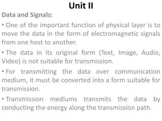
Unit II. Data and Signals: One of the important function of physical layer is to move the data in the form of electromagnetic signals from one host to another. The data in its original form (Text, Image, Audio, Video) is not suitable for transmission.

Unit II
E N D
Presentation Transcript
Unit II Data and Signals: One of the important function of physical layer is to move the data in the form of electromagnetic signals from one host to another. The data in its original form (Text, Image, Audio, Video) is not suitable for transmission. For transmitting the data over communication medium, it must be converted into a form suitable for transmission. Transmission mediums transmits the data by conducting the energy along the transmission path.
Unit II Analog and Digital: Both data and signals which represents data are of two forms Analog Digital Analog and Digital Data: The data that we want to transport can be analog or digital. Analog data refers to the information that is continuous in nature. Digital data refers to the information that is discrete (Non continuous) in nature.
Unit II Analog and Digital: Examples of analog data are Human Voice, Temperature etc. Examples of digital data are Data Stored in computers memory. Analog data can be converted into analog or digital signals. Digital data can be converted into digital signal. Analog data is going to take continuous values. Digital data is going to take discrete values.
Unit II Analog and Digital: Analog and Digital Signals: As data can be analog or digital, the signals which carry the data can also be analog or digital. An analog signal contains infinite values over a period of time. A digital signal contains definite values for the given period of time.
Unit II Analog and Digital: Analog and Digital Signals:
Unit II Analog and Digital: Periodic and No periodic Signals: Both analog and digital signals can be periodic or non periodic. A periodic signal repeats a specific pattern for a given time interval called as period. The completion one full pattern is called as a cycle. A non periodic signal does not shows or repeats as per a specific pattern for the given time period. In data communication we use periodic analog signals because they require less bandwidth and non periodic digital signals as they can represent variation in data.
Unit II Analog and Digital: Periodic Analog Signals: Periodic analog signals can be classified as Simple Composite A simple periodic analog signal can not be decomposed into simpler signals. Ex. Sine Wave A composite periodic analog signal can be decomposed into multiple sine waves. Sine Wave: A sine wave is the most fundamental form of periodic analog signal. A sine wave can be represented using three parameters
Unit II Analog and Digital: Peak Amplitude Frequency Phase
Unit II Analog and Digital: Peak Amplitude: The peak amplitude of a signal is the highest value attained by the signal. It reflects the energy it carries. For electrical signals it is measured in volts.
Unit II Analog and Digital: Period and Frequency: Period refers to the time a signal takes to complete one cycle. Frequency refers to the number of periods or cycles in one second. The relation between period and frequency is Period is normally expressed in seconds and frequency is expressed in Hertz.
Unit II Analog and Digital: Period and Frequency:
Unit II Analog and Digital: Period and Frequency:
Unit II Analog and Digital: Period and Frequency: Another way to look at frequency is that it shows the rate of change of a signal. If the signal changes rapidly in a short time it has high frequency and vice versa. If a signal does not changes at all its frequency is zero. If the signal changes from one level to another level in no time its frequency is infinite.
Unit II Analog and Digital: Phase: The term Phase shows the position of the waveform with respect to time. It reflects the distance travelled by a waveform in one cycle. It is measured in degrees or radians. Looking at the waveform we can conclude that A sine wave with phase of 0 degrees is not shifted. A sine wave with a phase of 90 degrees is shifted to the left by ¼ cycle. A sine wave with a phase of 180 degrees is shifted to the left by ½ cycle.
Unit II Analog and Digital: Phase:.
Unit II Analog and Digital: Wavelength: It is a term that is used to bind the frequency of a signal to the propagation speed of the medium. The frequency of the medium is independent of the medium but wavelength depends upon both frequency and medium.
Unit II Analog and Digital: Time Domain and Frequency: In all previous waveforms the signal is represented using time domain representation. The time domain representation shows changes in the signal amplitude with respect to time. In time domain plot phase is not shown explicitly. To show the relation between amplitude and frequency of a signal we use frequency domain plot. In frequency domain plot peak amplitude value of the signal and frequency are shown. Changes in one period are not shown in the frequency domain plot.
Unit II Analog and Digital: Time Domain and Frequency:
Unit II Analog and Digital: Time Domain and Frequency: The advantage of frequency domain plot is that we can easily see the values of peak amplitude and frequency of a signal. In this plot the position of the spike shows frequency and the height shows the amplitude. The frequency domain plot is more useful when we are dealing with more than one sine waves. Figure shows three sine waves in time domain and its frequency domain representation
Unit II Analog and Digital: Time Domain and Frequency:
Unit II Analog and Digital: Composite Signals: A composite signal is made up of many sine waves. Simple sine waves are not useful for data communication. A composite signal is actually a combination of many simple sine waves with different amplitude, frequency and phase. A composite signal can be periodic or non periodic. A Periodic composite signal can be decomposed into a series of simple sine waves with discrete frequencies that have integer values (1, 2, 3 …). A Non Periodic composite signal can be decomposed into a combination of infinite number of sine waves with continuous frequencies that have real values (1, 2, 3 …).
Unit II Analog and Digital: Composite Signals: Figure shows a composite periodic signal
Unit II Analog and Digital: Composite Signals: Figure shows a decomposed composite periodic signal both in time and frequency domain
Unit II Analog and Digital: Composite Signals: Figure shows a non periodic composite signal both in time and frequency domain
Unit II Analog and Digital: Bandwidth: The range of frequencies contained in an composite signal is called as Bandwidth. The bandwidth is usually difference between two frequencies. For Ex. If the range of frequencies contained in a composite signal is 2000 Hz to 5000 Hz. Then its bandwidth is 5000-2000 = 3000 Hz. Figure shows two composite signals, one periodic and other non periodic. For periodic signals the bandwidth contains all integer frequencies. For non periodic signals the bandwidth is of same range but contains continuous frequencies.
Unit II Analog and Digital: Bandwidth:
Example 3.11 A periodic signal has a bandwidth of 20 Hz. The highest frequency is 60 Hz. What is the lowest frequency? Draw the spectrum if the signal contains all frequencies of the same amplitude. Solution Let fh be the highest frequency, fl the lowest frequency, and B the bandwidth. Then The spectrum contains all integer frequencies. We show this by a series of spikes (see Figure 3.14).
Unit II Analog and Digital: Bandwidth:
Example 3.12 A nonperiodic composite signal has a bandwidth of 200 kHz, with a middle frequency of 140 kHz and peak amplitude of 20 V. The two extreme frequencies have an amplitude of 0. Draw the frequency domain of the signal. Solution The lowest frequency must be at 40 kHz and the highest at 240 kHz. Figure 3.15 shows the frequency domain and the bandwidth.
Unit II Digital Signals: The information that we want to communicate can be represented with the help of digital signals also. In digital signals for example a binary 1 can be encoded using a positive voltage level and a binary 0 can be encoded using a zero voltage level. Also a digital signal can have more than two voltage levels. If we represent data using more than two voltage levels in digital signals then we can transmit more than 1 bit using each voltage level. Figure shows a digital signal using different voltage levels
Unit II Digital Signals:
Unit II Digital Signals: As shown in figure, for first case we are transmitting 1 bit using each voltage level. For the second case we can transmit two bits using each voltage level. In general if a signal has L levels each level require Log2 L bits.
Example 3.16 A digital signal has eight levels. How many bits are needed per level? We calculate the number of bits from the formula Each signal level is represented by 3 bits.
Example 3.17 A digital signal has nine levels. How many bits are needed per level? We calculate the number of bits by using the formula. Each signal level is represented by 3.17 bits. However, this answer is not realistic. The number of bits sent per level needs to be an integer as well as a power of 2. For this example, 4 bits can represent one level.
Unit II Digital Signals: Bit Rate: Most of the digital signals are non periodic. Therefore frequency and phase are not appropriate characteristics. To describe digital signals a term called as Bit Rate is used. It is defined as the number of bits transmitted in one second. The unit of bit rate is bits per second (BPS)
Example 3.18 Assume we need to download text documents at the rate of 100 pages per minute. What is the required bit rate of the channel? Solution A page is an average of 24 lines with 80 characters in each line. If we assume that one character requires 8 bits, the bit rate is
Example 3.19 A digitized voice channel, as we will see in Chapter 4, is made by digitizing a 4-kHz bandwidth analog voice signal. We need to sample the signal at twice the highest frequency (two samples per hertz). We assume that each sample requires 8 bits. What is the required bit rate? Solution The bit rate can be calculated as
Unit II Digital Signals: Bit Length: Bit length of digital signal is similar to that of wavelength for a analog signal. Bit length is the distance occupied by a bit on the transmission medium. Thus Bit Length = Propagation Speed * Bit Duration
Unit II Digital Signal as Composite Analog Signal: Using the concept of Fourier analysis a digital signal can be treated as composite analog signal. The time domain representation of digital signal contains vertical and horizontal line segments. A vertical line in time domain shows infinite frequency (Sudden change in zero time). A horizontal line in time domain shows zero frequency (No change in time) Thus in a digital signal going from zero frequency to infinite frequency shows the domain contain all intermediate frequencies.
Unit II Digital Signal as Composite Analog Signal: Fourier analysis can be used for the decomposition of Digital Signals. If the digital signal is periodic then the decomposed signal has a frequency domain representation with an infinite bandwidth and discrete frequencies. If the digital signal is non periodic then the decomposed signal has a frequency domain representation with an infinite bandwidth but the frequencies are continuous.
Unit II Digital Signal as Composite Analog Signal:
Unit II Transmission of Digital Signals: A digital signal can be treated as composite analog signal having frequencies between zero and infinity. It can be periodic or non periodic. For data communication we prefer non periodic digital signal. A digital signal can be transmitted using one of the two methods Baseband Transmission Broadband Transmission ( Using Modulation)
Unit II Transmission of Digital Signals: Baseband Transmission: In this method of transmission a digital signal is transmitted on the transmission medium without changing it to analog signal.
Unit II Transmission of Digital Signals: For baseband transmission we require a low pass channel (Medium). A low pass channel is a channel whose frequency starts from zero. This is a case when we have a dedicated medium with a bandwidth constituting only one channel. For example a cable connecting two computers using point to point link. We can also have a bus (Multipoint Link), but with a restriction that only two stations can communicate at a time. Figure shows two low pass channels one having narrow bandwidth and other with infinite bandwidth.
Unit II Transmission of Digital Signals:
Unit II Transmission of Digital Signals: Baseband transmission of digital signals that preserves the shape of the signals is possible if we have a low pass channel with a very wide bandwidth. Two computers can communicate with each other using baseband transmission if the communication medium is having wide bandwidth such as coaxial cable or fiber optic. Figure shows baseband transmission with dedicated medium
Unit II Transmission of Digital Signals:
Unit II Transmission of Digital Signals: For transmitting digital signal using a medium with low bandwidth we approximate digital signal to a analog signal. The level of approximation depends upon the bandwidth available. In this case the required bandwidth is proportional to the bit rate. It means that if we want to send bits faster we need more bandwidth. Figure shows simulation of digital signal with first three harmonics
Unit II Transmission of Digital Signals: