Download
1 / 14
140 likes | 346 Vues
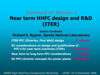
Summary of Session 1 Near term HHFC design and R&D (ITER) Session Coordinator Richard E. Nygren, Sandia National Laboratories ITER PFC (Divertor, First Wall) design M. Merola EU considerations on design and qualification of PFC's for near term machines (ITER) P. Lorenzetto

E N D
Summary of Session 1 • Near term HHFC design and R&D • (ITER) • Session Coordinator • Richard E. Nygren, Sandia National Laboratories • ITER PFC (Divertor, First Wall) designM. Merola • EU considerations on design and qualification of PFC's for near term machines (ITER)P. Lorenzetto • Near term to long term PFC considerations R. Nygren • EU PFC/divertor concepts for power plants P. Norajitra
Summary of Session 1: Near term HHFC design and R&D (ITER) • ITER PFC (Divertor, First Wall) designM. Merola Divertor System Remote Handling Power Handling Thermo-hydraulics HHF Technologies PFCs Cassette Body Divertor Rails analysis testing configuration
Summary of Session 1: Near term HHFC design and R&D (ITER) • ITER PFC (Divertor, First Wall) designM. Merola • Divertor Design is completed • Extensive integration work carried out on the interfacing systems • Extensive R&D has been carried out by EU, JA, RF DAs • All concerned DAs have demonstrated the technical capability to manufacture divertor components with adequate heat flux performance • Divertor design process has progressed over the years with constant consideration for the maintenance process and close interaction with RH equipment / process developers. However, RH remains a challenge. • FW and Shield design has been modified with respect to the 2001 baseline • A First Wall shape is being developed which both shadows leading edges, and provides for a generous RH access aperture • Different design solutions may be needed for toroidal or poloidal position of unit • HHF technology is required in some regions, but removes need for start-up limiters • The complex procurement sharing adds a further challenge
Summary of Session 1: Near term HHFC design and R&D (ITER) • ITER PFC (Divertor, First Wall) designM. Merola Review of detailed design of divertor and FW. Discussion clarified points about the design of the ITER divertor. A question was asked about “lessons learned.” RichardN noted the EU fusion program and Tore Supra in particular had established a strong collaboration with Plansee over many years that served the project well when they ran into difficulty with a high rejection rate of parts.
Summary of Session 1: Near term HHFC design and R&D (ITER) • EU considerations on design and qualification of PFC's for near term machines (ITER) P. Lorenzetto Extensive manufacturing and testing reviewed. CuCrZr /BeHIPping
Summary of Session 1: Near term HHFC design and R&D (ITER) • EU considerations on design and qualification of PFC's for near term machines (ITER) P. Lorenzetto • EU has a successful R&D programme over more than 15 years to • develop reference fabrication paths for the Divertor and FW, • investigate and develop alternative fabrication methods to enhance competition, reduce technical risk and fabrication cost. • R&D continues to • further improve the performances and increase engineering margins, • develop acceptance tests and criteria for the series production, • develop repair techniques. • Qualification programmes for the procurement of ITER In-Vessel components have started. • Close collaboration between the main partners, IO, DAs including Industry and Laboratories is essential for the success of the Project.
Summary of Session 1: Near term HHFC design and R&D (ITER) • EU considerations on design and qualification of PFC's for near term machines (ITER) P. Lorenzetto Questions/discussion: RobG – copper? Design being revised to have more Cu on top. RobG – fingers 10cm thick? Yes, new design may be a bit thinner. Breeding requires different FW than ITER has. IO always felt need to go to higher HF, testing up to 3MW/m2. Be-Cu irrad to 0.6 dpa; new campaigns include joined mockups. FWQM (Nuclear Research Institute, (Rèz, Czech R.) DennisW – lots of different R&D; would it have been better to pick a single solution, e.g. all PFCs 10MW/m2. Yes, maybe – we could use the divertor technology. RichardN – maybe not; divertor has its own RAMI.
Summary of Session 1: Near term HHFC design and R&D (ITER) • Near term to long term PFC considerations R. Nygren “Greenwald Panel” Recommendation 4. .. 9 major initiatives. I-1. .. predictive plasma modeling and validation .., I-2. Extensions to ITER AT capabilities .. burning AT regimes I-3. Integrated advanced burning physics …facility .. dedicated I-4. Integrated experiment for PWI/PFCs .. steady-state .. non-DT I-5. .. disruption-free concepts .. performance extension device .. I-6. .. advanced computer modeling and laboratory testing .. single-effects science for major fusion technology issues, I-7. Materials qualification facility … (IFMIF). I-8. Component development/testing program … multi-effect issues in critical technology .. breeding/blanket .. first wall I-9. Component qualification facility.. high availability.. heat flux .. neutron fluence .. DT device .... (CTF).
Summary of Session 1: Near term HHFC design and R&D (ITER) • Near term to long term PFC considerations R. Nygren PROGRAM & DESIGN INTEGRATION knowledge .. sufficient to design and build, with high confidence, Recall some excerpts from the “Greenwald” panel report: 9. PFCs: Understand .. materials and processes … design replaceable components that can survive .. I-3. Integrated advanced burning physics …facility .. dedicated I-4. Integrated experiment for PWI/PFCs .. steady-state .. non-DT I-8. Component development/testing program … multi-effect issues in critical technology .. breeding/blanket .. first wall
Summary of Session 1: Near term HHFC design and R&D (ITER) • Near term to long term PFC considerations R. Nygren Questions/discussion: ReneR – integrated PSI/PFC? RichardN -Facility would need temperature, availability, flexibility and dedicated device. ReneR – can we use ITER for a TDivM? FrederickE – a proposed use of Tore Supra for new mat’ls etc received lots of discussion but was rejected by mgmt. MarioM also did not believe ITER could accept this mission. RobG – ITER will provide disruption loads that no other (less expensive) device can. DW – all compact D/T systems have these loads. Rob – He cooling takes large ducts, this is a problem.
He flow 600˚C 10 MPa Flat W armor brazed to W alloy thimble W-to-steel transition (brazed) ODS EUROFER structure Summary of Session 1: Near term HHFC design and R&D (ITER) • EU PFC/divertor concepts for power plants P. Norajitra Updated design 2008 Outlet 700˚C In HHF tests at Efremov, a single module mockup with a WL-10 thimble survived a heat load of 11.6 MW/m2 with He (inlet) at 500C.
Summary of Session 1: Near term HHFC design and R&D (ITER) • EU PFC/divertor concepts for power plants P. Norajitra • Design requirements • Complete a functioning, reliable divertor by 2038 • 10 (nominal) -15 MW/m2 peak; consider heat flux profile, moving peak and 100-1000 cycles • Use same blanket and divertor coolant type (power conversion system PCS simplification) • Exploit divertor heat (economics): coolant temperature as high as possible; keep pumping power as low as possible the pumping power and integrate the divertor heat into PCS • Use exclusively low activation materials • First material screening results: • Only W/alloy are suitable as PFC material (Tm, k, low sputtering) • ODS ferritic steel is currently the best candidate for divertor main structure • Drawbacks (1): a) brittleness, b) not developed for use as structure, c) uncertainties in properties (e.g. DBTT, RCT) and unknown factors (e.g. irradiation, fabrication, history,...), d) anticipated working temperature window (irradiated W) of 600-1300°C (requirement for material R&D), those for ODS Eurofer to be 300-700°C, respectively. • Very narrow gap for thermo-hydraulics, He temperature between 600 inlet and 700°C outlet. • Drawbacks (2): large mismatch between W/W alloy and ODS Eurofer requires a sophisticated transition joint (ratchetting compensating)
Summary of Session 1: Near term HHFC design and R&D (ITER) • EU PFC/divertor concepts for power plants P. Norajitra Clear lesson: Not enough safety margins left to be credited for other uncertainties in design! Design status 2008: 10 MW/m2 heat removal by He has been demonstrated out-of-pile under real DEMO conditions R&D in fabrication and joining technologies running with goal of reaching high quality, high reliability and mass production From design point of view, requirements for nominal design with constant load are currently Physics: suppression of ELMs, disruption and VDEs (safety, reliability, availability, attractiveness and marketability of the FPP) can be treated later as abnormal conditions in safety study. Materials R&D: W alloys with low DBTT, advanced (nano) ferritic steels which enables higher working temperature of 800-900°C Characterisation of the above divertor materials including irradiation material properties
Summary of Session 1: Near term HHFC design and R&D (ITER) • EU PFC/divertor concepts for power plants P. Norajitra Questions/discussion: Starting to use other (non Co) braze. RichardN – Failure of armor without breaking vac boundary is very important result. Heat/temp leads to density reduction that can cause flow instability. Here, grid for flow jets has greatest P and evens flow. ClementW – disruptions? Not designed to withstand disruptions. FrederickA – disruptions? ReneR – in US we assume disruptions will be largely mitigated (only a few), and then design PFC to take melting. RobG – inlet? 170mm dia pipe vs.73mm for water in ITER. MarioM – probability is zero for ITER test of He-cooled divertor sector. DennisW – what is weak link, thermal cycling, joints? W has cracks and microcracks from machining, also thermal-hydraulics. PartickL – but there are W in pressure boundary? Reith – parts joined with non-optimized parts and braze. Lesson: Not enough safety margins to cover other design uncertainties!


![Progressive EEnhancement [EECI 2011]](https://cdn4.slideserve.com/7565210/progressive-nhancement-dt.jpg)