Download
1 / 23
230 likes | 375 Vues
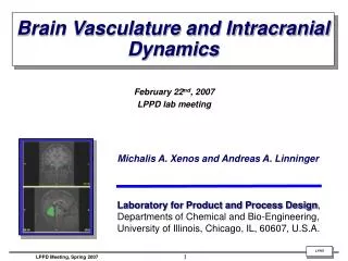
Brain Vasculature and Intracranial Dynamics. February 22 nd , 2007 LPPD lab meeting. Michalis A. Xenos and Andreas A. Linninger Laboratory for Product and Process Design , Departments of Chemical and Bio-Engineering, University of Illinois, Chicago, IL, 60607, U.S.A.

E N D
Brain Vasculature and Intracranial Dynamics February 22nd, 2007 LPPD lab meeting Michalis A. Xenos and Andreas A. Linninger Laboratory for Product and Process Design, Departments of Chemical and Bio-Engineering, University of Illinois, Chicago, IL, 60607, U.S.A.
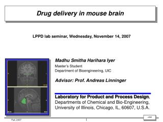
Motivation for studying Intracranial Dynamics • Many biological phenomena in the brain need better interpretation • Large deformation of biological tissues under hydrocephalic conditions. • Interaction of vasculature with soft brain tissue. • Fundamental transport processes in soft tissues are poorly understood. • Interpretation of experiments is inadequate. Hydrocephalic Brain MRI Normal Brain MRI
Continuity Momentum Distensibility of vasculature are equal for i = 1, …,n Equations of motion for a vessel, Bifurcations and Unions Straight tube parent children l : tube length F: Poiseuille coef. E : Young modulus A0 : Initial cross sectional area p* : External pressure Unknowns: fin , p , A Bifurcation child parents Union
T’2 T2 T4 T4 T1 T1 T3 Bifurcated tubes vs. lumped tubes
Blood signals and fitting procedure Pulsatile blood pressure from MRI
Arterial spectrum Ventricular spectrum Phase lag Spectral analysis for blood and ventricular signals from MRI data Applying FFT the spectrum for both pulses :
Model Generator and obtained networks Model Generator Blood network same to Zagzoule’s
A simple blood flow model – Zagzoule network Hademenos, Massoud, The physics of Cerebrovascular Diseases, 1998
QA QFfr Subarachnoid space (SAS) (r) QFfb Arteries (a) QFcf Ventricles (f) Qac QFpf Qap Choroid Plexus (p) Capillaries (c) Qpc Qpv QFcb Qcv QFfv Venous Sinus (n) Qvn QFbr Veins (v) QFbv Brain (b) QFri QFrn QA QFir Spinal Cord (s) A holistic brain compartmental model Blood flow CSF flow
Continuity Momentum Continuity Distensibility of vasculature Momentum Total stress p* d solid p p fluid Open vs. Closed network systems Open system Closed system
Egnor’s mathematical model Newton’s Law or we differentiate both sides of the above equation Forcing function the particular solution of the above equation is Damping force Elastic resistance Pulsatile resistance Elastic force Resonance : In an oscillating system with one degree of freedom, resonance is the state of minimal impedance. Acceleration
RLC vs. 2nd order oscillators • Series RLC Circuit notations: • V - the voltage of the power source (V) • I - the current in the circuit (A) • R - the resistance of the resistor (Ohms = V/A); • L - the inductance of the inductor (H = V·s/A) • C - the capacitance of the capacitor (F = C/V = A·s/V) • Given the parameters v, R, L, and C, the solution for the current i using Kirchhoff's voltage law is: • For a time-changing voltage V(t), this becomes • Rearranging the equation (dividing by L and differentiating with respect to t gives the following second order differential equation: Damping factor • We now define two key parameters: Resonance frequency
Continuity Momentum Distensibility of vasculature Straight tube R C Electrical analogy (RC) Our model vs. RLC I
Assumptions of Egnor’s model 1. Intracranial CSF pulsations are normally synchronous with arterial pulsations. 2. Normal intracranial CSF pulsations are of similar amplitude and morphology in the ventricles and the subarachnoid space. 3. Arterial pulsations are normally filtered from the cerebelar circulation, so the capillary blood flow is nearly smooth (the windkessel mechanism). Oscillations of CSF with a single degree of freedom are described by the same differential equation that describes the oscillations of electrons in an alternating current electrical circuit Windkessel Effect The mechanism by which arterial pulsations are progressively dissipate to render the capillary circulation almost pulseless is called the windkessel effect. Egnor et al, Pediatric Neurosurgery, 2001; 2002
The role of resonance in Egnor’s model and the reality • With the help of resonance Egnor assumes that the Intracranial CSF pulsations are synchronous with arterial pulsations. This is not true: Phase lag: aqueduct: – 52.5 ± 16.5o prepontine cistern: – 22.1 ± 8.2o C-2: +5.1 ± 10.5o (consistent with flow synchronous with the arterial pulse) Wagshul et al, J. Neurosurg, 2006 Zhu et al, J. MRI, 2006
Conclusions • Current systems describe the brain until a point • Electrical analogies of the models • Egnor’s model and his assumptions were presented • The flow between blood and CSF has a phase lag and the assumption of synchronous pulsations is not valid • Advancement of these models with the inclusion of porosity! • Future steps – distributed systems