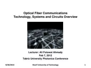
Optical Fiber Communications
Optical Fiber Communications. Lecture 10. Topics. Single Mode Fiber Mode Field Diameter Propagation Modes in Single Mode Fiber Graded Index Fiber. Single Mode Fiber. Single Mode fiber are constructed by letting dimensions of core diameter be a few wavelengths and

Optical Fiber Communications
E N D
Presentation Transcript
Optical Fiber Communications Lecture 10
Topics • Single Mode Fiber • Mode Field Diameter • Propagation Modes in Single Mode Fiber • Graded Index Fiber
Single Mode Fiber • Single Mode fiber are constructed by • letting dimensions of core diameter be a few wavelengths and • by having small index difference between core and cladding • In practice core cladding index difference varies between 0.1 and 1.0 percent • Typical single mode fiber may have a core radius of 3 micron and NA =0.1 at wavelength = 0.8 micron
Mode Field Diameter • Geometric distribution of light in propagation mode is important when predicting performance characteristics. • Mode Field Diameter (MFD) is analogues to core diameter in multimode fibers except not all light that propagates is carried in the core • Many models for characterizing MFD with main consideration of how to approximate electric field distribution
MFD • Assume electric field distribution to be Gaussian • Where r is radius, Eo is field at zero radius, and Wo is the width of the electric field distribution • Take width 2Wo of MFD to be 2e-1radius of optical electric field (e-2 of optical power)
MFD • The MFD width 2Wo can be defined for LP01 mode as
Propagation Modes in Single Mode Fiber • In single mode fiber there are two independent degenerate propagation modes • These modes are similar but their polarization planes are orthogonal • Electric field of light propagating along the fiber is linear superposition of these two polarization mode
contd • Choose one of the modes to have its transverse electric field along x direction and the other in y direction • In ideal fiber, two modes are degenerate with equal propagation constants and will maintain polarization state injected into the fiber • In actual fiber there are imperfections, such as asymmetrical lateral stress, noncircular cores and variations in refractive index profiles • These imperfections break circular symmetry
contd • The modes propagate with different phase velocities and the difference between their effective refractive indices is called birefringence • Or • If light is injected into the fiber so that both modes are excited, then one will be delayed in phase
contd • When this phase difference is an integral m*pi, the two mode will beat at this point and input polarization state will be reproduced. • The length over which this beating occurs is the fiber beat length
Example • A single mode optical fiber has a beat length of 8 cm at 1300nm, the modal birefringence • Or
Graded Index Fiber Structure • In graded index fiber, core refractive index decreases continuously with increasing radial distance r from center of fiber and constant in cladding • Alpha defines the shape of the index profile • As Alpha goes to infinity, above reduces to step index • The index difference is
contd • NA is more complex that step index fiber since it is function of position across the core • Geometrical optics considerations show that light incident on fiber core at position r will propagate only if it within NA(r) • Local numerical aperture is defined as • And
contd • Number of bound modes
Examples If a = 9.5 micron, find n2 in order to design a single mode fiber, if n1=1.465. Solution, The longer the wavelength, the larger refractive index difference is needed to maintain single mode condition, for a given fiber
Examples • Compute the number of modes for a fiber whose core diameter is 50 micron. Assume that n1=1.48 and n2=1.46. Wavelength = 0.8 micron. • Solution For large V, the total number of modes supported can be estimated as
Example • What is the maximum core radius allowed for a glass fiber having n1=1.465 and n2=1.46 if the fiber is to support only one mode at wavelength of 1250nm. • Solution
HW • Due 2/11/08 • 2-2 • 2-8 • 2-11 • 2-18 • 2-19 • 2-21 • 2-24 • 2-25 • 2-27 • 2-28