Useful Equations in Planar Rigid-Body Dynamics
420 likes | 1.52k Vues
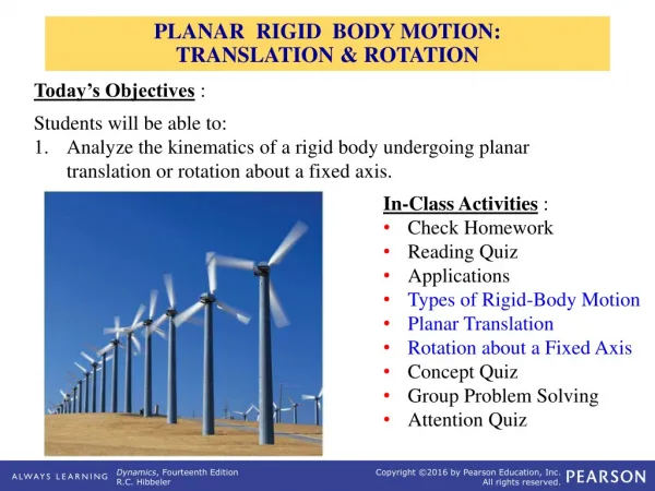
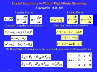
Useful Equations in Planar Rigid-Body Dynamics. Kinematics (Ch. 16). Linear Motion. Angular Motion. r = r { t }. Constant linear Acceleration. Constant Angular Acceleration. 2D Rigid Body Kinematics, relative velocity and acceleration equations.

Useful Equations in Planar Rigid-Body Dynamics
E N D
Presentation Transcript
Useful Equations in Planar Rigid-Body Dynamics Kinematics (Ch. 16) Linear Motion Angular Motion r = r{t} Constantlinear Acceleration Constant AngularAcceleration 2D Rigid Body Kinematics, relative velocity and acceleration equations Mechanical Engineering
Useful Equations in Planar Rigid-Body Dynamics Equations of Motion (Ch. 17) F= ma Translation • Rotation about the axis thru the center of gravity MG= IGα • Rotation about a fixed axis thru point O MO= IOα MO= (MO)k Mass Moment of Inertia Parallel Axis Theorem Radius of Gyration Mechanical Engineering
Work and Energy (Ch. 18) Total kinetic energy of a rigid body rotating and translating Principle of Work and Energy Work done by a moment Work done by a force Work done by gravity and spring Due to gravity Due to torsional spring Due to linear spring Conservation of Energy Mechanical Engineering
Linear and Angular Momentum (Ch. 19) Principle of Angular Impulse and Momentum Principle of Linear Impulse and Momentum Non-Centroidal Rotation Mechanical Engineering
Solving Dynamic Problems • Newton’s second law (force and acceleration method) may be the most thorough method, but can sometimes be more difficult. • If all forces are conservatives (negligible friction forces), the conservation of energy is easier to use than the principle of work and energy. • Conservation of linear and angular impulse and momentum can be used if the external impulsive forces are zero (conservation of linear impulse and momentum, impact) or the moment of the forces are zero (conservation of angular momentum) • Energy method tends to be more intuitive and easier to use. • Momentum method is less intuitive, but sometime necessary. Mechanical Engineering
Solving Dynamic Problems The type of unknowns and given information could point to the best method to use. • Accelerationsuggests that the equations of motion should be used, kinematic equations are used when there are no forces or moments involved. • Displacement or velocity (linear or angular) indicates that the work and energy method is easier to use. • Time suggests that the impulse and momentum method is useful • If springs (linear or torsional) exist, the work and energy is a useful method. Mechanical Engineering
Example 1 A homogeneous hemisphere of mass M is released from rest in the position shown. The moment of inertia of a hemisphere about its center of mass is (83/320)mR2. What is the angular velocity when the object’s flat surface is horizontal? Conservation of energy Mechanical Engineering
Example 2 • The angular velocity of a satellite can be altered by deploying small masses attached to very light cables. The initial angular velocity of the satellite is 1 = 4 rpm, and it is desired to slow it down to 2 = 1 rpm. • Known information: • IA = 500 kg·m2 (satellite) • mB = 2 kg (small weights) • What should be the extension length d to slow the satellite as required? Mechanical Engineering
Example 2 The only significant forces and moments in this problem are those between the two bodies, so conservation of momentum applies. The point about the deployed masses being small mean they have insignificant I, and the (r x mv) for the main body is zero because it spins about its center of mass (r = 0). Mechanical Engineering
Example 3 The left disk rolls at constant 2 rad/s clockwise. Determine the linear velocities of joints A and B, vA and vB. Also determine the angular velocities ABand BD. B A Relative velocity equation for points A and C D C Mechanical Engineering
Example 3 Relative velocity equation for points B and D B A D C Relative velocity equation for points B and A Mechanical Engineering
Example 3 Setting the iandj component equal: Mechanical Engineering
Example 4 • The system shown is released from rest with the following conditions: • mA=5 kg, mB=10 kg, Ipulley=0.2 kg·m2, R = 0.15 m • No moment is applied at the pivot. What is the velocity of mass B when it has fallen a distance h= 1 m? The only force or moment that exists and does work is gravity, and it is a conservative force, so conservation of energy applies. Mechanical Engineering
Example 4 C 2 A B 1 0 Mechanical Engineering
Example 5 If bar AB rotates at 10 rad/s, what is the rack velocity vR? Relative velocity equations Mechanical Engineering
Example 5 Mechanical Engineering
Example 5 i components j components Mechanical Engineering
Example 6 Mechanical Engineering
Example 6 Force and motion diagrams for the plate. Kinematics G Relative acceleration equation for points G and A A Mechanical Engineering
Example 6 Mechanical Engineering
Example 7 Force diagram Motion diagram Mechanical Engineering
Example 7 G Mechanical Engineering
Example 8 vB = 21 AB vC slider dir. vC/B CB = (vC/B)/CB Mechanical Engineering
Example 8 Mechanical Engineering
Example 9 At the instant shown, the disk is rotating with an angular velocity of and has an angular acceleration of α. Determine the velocity and acceleration of cylinder B at this instant. Neglect the size of the pulley at C Use position coordinate method Determine the length s = AC in terms of the angle θ( Law of Cosines) Mechanical Engineering
Example 9 Mechanical Engineering
Example 10 Mechanical Engineering
Example 10 Mechanical Engineering