Download
1 / 23
240 likes | 361 Vues
Study translation and rotation of a body in planar motion. Learn to analyze velocity and acceleration in various applications. Differentiate general plane motion. Explore how all points in a rigid body subjected to translation move with the same velocity and acceleration. Discover the equations for angular velocity and acceleration in rotation about a fixed axis. Enhance your design skills for machinery components.

E N D
Chapter 5 Planar Kinematics of a Rigid Body Dr Fauziah Mat Applied Mechanics Division School of Mechatronic Engineering Universiti Malaysia Perlis (UniMAP) fauziah@unimap.edu.my
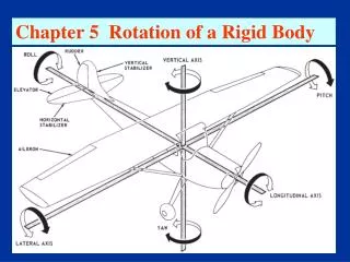
PLANAR RIGID BODY MOTION: TRANSLATION & ROTATION • Today’s Objectives : • Students will be able to: • Analyze the kinematics of a rigid body undergoing planar translation or rotation about a fixed axis. • In-Class Activities : • Applications • Types of Rigid-Body Motion • Planar Translation • Rotation about a Fixed Axis • Group Problem Solving
APPLICATIONS Passengers on this amusement ride are subjected to curvilinear translation since the vehicle moves in a circular path but they always remains upright. If the angular motion of the rotating arms is known, how can we determine the velocity and acceleration experienced by the passengers? Why would we want to know these values? Does each passenger feel the same acceleration?
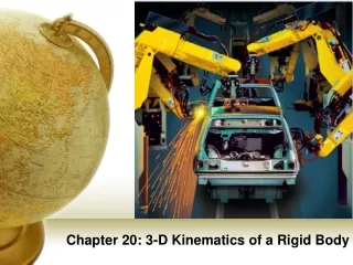
APPLICATIONS (continued) Gears, pulleys and cams, which rotate about fixed axes, are often used in machinery to generate motion and transmit forces. The angular motion of these components must be understood to properly design the system. To do this design, we need to relate the angular motions of contacting bodies that rotate about different fixed axes. How is this different than the analyses we did in earlier chapters?
RIGID BODY MOTION (Section 16.1) There are cases where an object cannot be treated as a particle. In these cases the size or shape of the body must be considered. Rotation of the body about its center of mass requires a different approach. For example, in the design of gears, cams, and links in machinery or mechanisms, rotation of the body is an important aspect in the analysis of motion. We will now start to study rigid body motion. The analysis will be limited to planar motion. A body is said to undergo planar motion when all parts of the body move along paths equidistant from a fixed plane.
PLANAR RIGID BODY MOTION There are three types of planar rigid body motion.
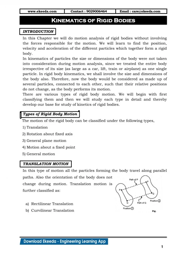
PLANAR RIGID BODY MOTION (continued) Translation: Translation occurs if every line segment on the body remains parallel to its original direction during the motion. When all points move along straight lines, the motion is called rectilinear translation. When the paths of motion are curved lines, the motion is called curvilinear translation.
PLANAR RIGID BODY MOTION (continued) Rotation about a fixed axis: In this case, all the particles of the body, except those on the axis of rotation, move along circular paths in planes perpendicular to the axis of rotation. General plane motion: In this case, the body undergoes both translation and rotation. Translation occurs within a plane and rotation occurs about an axis perpendicular to this plane.
PLANAR RIGID BODY MOTION (continued) An example of bodies undergoing the three types of motion is shown in this mechanism. The wheel and crank undergo rotation about a fixed axis. In this case, both axes of rotation are at the location of the pins and perpendicular to the plane of the figure. The piston undergoes rectilinear translation since it is constrained to slide in a straight line. The connecting rod undergoes curvilinear translation, since it will remain horizontal as it moves along a circular path. The connecting rod undergoes general plane motion, as it will both translate and rotate.
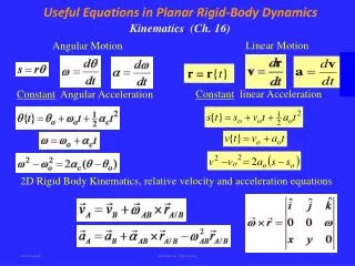
RIGID-BODY MOTION: TRANSLATION (Section 16.2) The positions of two points A and B on a translating body can be related by rB =rA + rB/A where rA&rB are the absolute position vectors defined from the fixed x-y coordinate system, andrB/A is the relative-position vector between B and A. Thevelocity at B is vB=vA+ drB/A/dt . Now drB/A/dt= 0 sincerB/A is constant. So,vB=vA, and by following similar logic, aB=aA. Note, all points in a rigid body subjected to translation move with the same velocity and acceleration.
Angular velocity, , is obtained by taking the time derivative of angular displacement: = d/dt (rad/s) + Similarly,angular acceleration is = d2/dt2 = d/dt or = (d/d) rad/s2 + RIGID-BODY MOTION: ROTATION ABOUT A FIXED AXIS (Section 16.3) When a body rotates about a fixed axis, any point P in the body travels along a circular path. The angular position of P is defined by q. The change in angular position, d, is called the angular displacement, with units of either radians or revolutions. They are related by 1 revolution = (2) radians
RIGID-BODY MOTION: ROTATION ABOUT A FIXED AXIS (continued) If the angular acceleration of the body is constant,a = aC, the equations for angular velocity and acceleration can be integrated to yield the set of algebraic equations below. = 0 +aC t q=q0 + 0 t + 0.5aC t2 2 = (0)2 + 2aC (q–q0) q0 and 0 are the initial values of the body’s angular position and angular velocity. Note these equations are very similar to the constant acceleration relations developed for the rectilinearmotion of a particle.
RIGID-BODY ROTATION: VELOCITY OF POINT P The magnitude of the velocity of P is equal to wr (the text provides the derivation). The velocity’s direction is tangent to the circular path of P. In the vectorformulation, the magnitude and direction of vcan be determined from the cross productofwand rp. Here rp is a vector from any point on the axis of rotation to P. v= w×rp =w×r The direction of v is determined by the right-hand rule.
RIGID-BODY ROTATION: ACCELERATION OF POINT P The acceleration of P is expressed in terms of its normal(an) andtangential(at) components. In scalar form, these are at = a r and an = w2 r. Thetangential component,at, represents the time rate of change in the velocity'smagnitude. It is directed tangent to the path of motion. The normal component, an, represents the time rate of change in the velocity’sdirection. It is directed towardsthecenterof the circular path.
Themagnitudeof the acceleration vector is a = (at)2 + (an)2 RIGID-BODY ROTATION: ACCELERATION OF POINT P (continued) Using the vectorformulation, the acceleration of P can also be defined by differentiating the velocity. a= dv/dt =dw/dt ×rP + w× drP/dt =a×rP+w× (w×rP) It can be shown that this equation reduces to a=a×r– w2r=at + an
To determine the motion of a point, the scalar equations v = w r, at = a r, an = w2r,and a = (at)2 + (an)2 can be used. ROTATION ABOUT A FIXED AXIS: PROCEDURE • Establish a sign conventionalong the axis of rotation. • If a relationship is known between any two of the variables (a,w,q, or t), the other variables can be determined from the equations: w= dq/dta = dw/dtadq=wdw • If ais constant, use the equations for constant angular acceleration. • Alternatively, the vector form of the equations can be used (withi, j, k components). • v = w×rP = w×r • a= at + an = a× rP + w × (w× rP) = a×r – w2r
EXAMPLE Given:The motor turns gear A with a constant angular acceleration, aA = 4.5 rad/s2, starting from rest. The cord is wrapped around pulley D which is rigidly attached to gear B. Find: The velocity of cylinder C and the distance it travels in 3 seconds. 1) The angular acceleration of gear B (and pulley D) can be related to aA. 2) The acceleration of cylinder C can be determined by using the equations of motion for a point on a rotating body since (at)D at point P is the same as ac. 3) The velocity and distance of C can be found by using the constant acceleration equations. Plan:
EXAMPLE (continued) Solution: 1) Gear A and B will have the same speed and tangential component of acceleration at the point where they mesh. Thus, at = aArA = aBrB (4.5)(75) = aB(225) aB = 1.5 rad/s2 Since gear B and pulley D turn together, aD = aB = 1.5 rad/s2 2) Assuming the cord attached to pulley D is inextensible and does not slip, the velocity and acceleration of cylinder C will be the same as the velocity and tangential component of acceleration along the pulley D. aC = (at)D = aD rD = (1.5)(0.125) = 0.1875 m/s2
EXAMPLE (continued) 3) Since aA is constant, aD and aC will be constant. The constant acceleration equation for rectilinear motion can be used to determine the velocity and displacement of cylinder C when t = 3 s (s0= v0 = 0): vc = v0 +aC t = 0 + 0.1875 m/s2(3 s) =0.563 m/s sc = s0 +v0 t+ (0.5) aC t2 = 0 + 0 + (0.5) 0.1875 m/s2 (3 s)2 =0.844 m
GROUP PROBLEM SOLVING Given: Gear A is given an angular acceleration aA= 4t3 rad/s2, where t is in seconds, and (A)0= 20 rad/s. Find: The angular velocity and angular displacement of gear B when t = 2 s. Plan: 1) Apply the kinematic equation of variable angularacceleration to find the angular velocity of gear A. 2) Find the relationship of angular motion between gear A and gear B in terms of time and then use 2 s.
GROUP PROBLEM SOLVING (continued) Solution: 1) Motion of Gear A : Applying the kinematic equation
GROUP PROBLEM SOLVING (continued) 2) Since gear B meshes with gear A, B= 36(0.05/ 0.15) = 12 rad/s B= 46.4(0.05/ 0.15) = 15.5 rad
End of the Lecture Let Learning Continue