Download
1 / 25
250 likes | 324 Vues
Ekeeda Provides Online Civil Engineering Degree Subjects Courses, Video Lectures for All Engineering Universities. Video Tutorials Covers Subjects of Mechanical Engineering Degree.

E N D
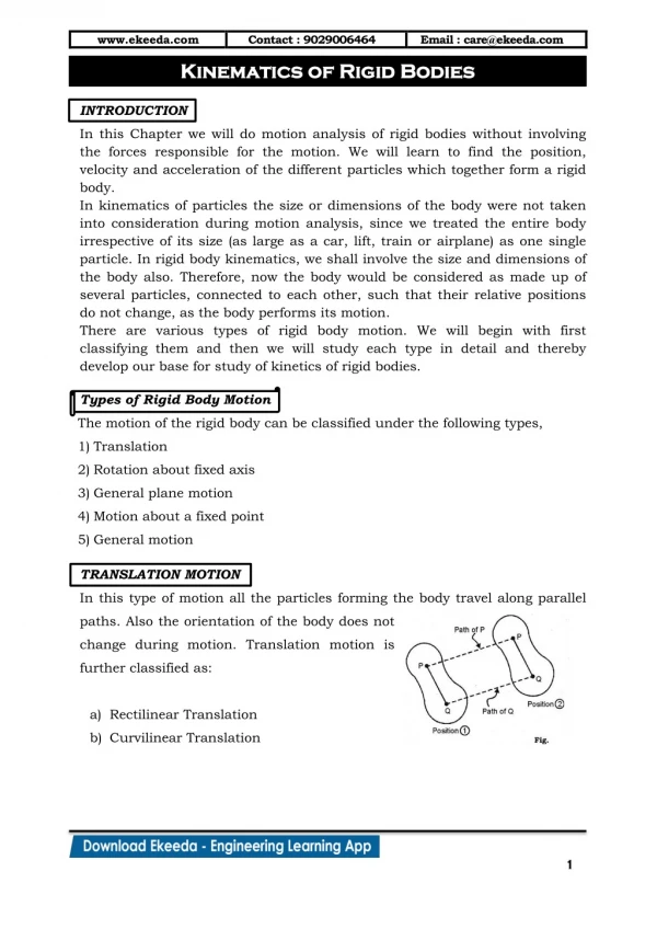
www.ekeeda.com Contact : 9029006464 Email : care@ekeeda.com P Kinematics of Rigid Bodies Kinematics of Rigid Bodies INTRODUCTION In this Chapter we will do motion analysis of rigid bodies without involving the forces responsible for the motion. We will learn to find the position, velocity and acceleration of the different particles which together form a rigid body. In kinematics of particles the size or dimensions of the body were not taken into consideration during motion analysis, since we treated the entire body irrespective of its size (as large as a car, lift, train or airplane) as one single particle. In rigid body kinematics, we shall involve the size and dimensions of the body also. Therefore, now the body would be considered as made up of several particles, connected to each other, such that their relative positions do not change, as the body performs its motion. There are various types of rigid body motion. We will begin with first classifying them and then we will study each type in detail and thereby develop our base for study of kinetics of rigid bodies. Types of Rigid Body Motion The motion of the rigid body can be classified under the following types, 1)Translation 2)Rotation about fixed axis 3)General plane motion 4)Motion about a fixed point 5)General motion TRANSLATION MOTION In this type of motion all the particles forming the body travel along parallel paths. Also the orientation of the body does not change during motion. Translation motion is further classified as: a)Rectilinear Translation b)Curvilinear Translation 1
www.ekeeda.com Contact : 9029006464 Email : care@ekeeda.com Rectilinear Translation In this type of translation motion, all the particles travel along straight parallel paths. Consider the motion of a body from position (1) to position (2). Here we note two things, firstly a straight line joining particles P and Q in position (1) maintains the same direction in position (2) This indicates that the orientation of the body remains the same throughout the motion. The second thing which is special to rectilinear translation motion, is that the path described by the various particles, such as P and Q in our example, are parallel and they are straight. Examples of rectilinear translation motion are, 1)A piston which travels in the fixed slot. 2)Motion of train on a straight track. 3)Motion of lift etc. Curvilinear Translation In this type of translation motion, all the particles travel along curved parallel paths. Consider the motion of a body from position (1) to position (2) Here we note that the line joining particles P and Q in position (1) has the same orientation in position (2) This is indicative of translation motion of the body. Further the path described by all the particles, such as P and Q in our example, are parallel and they are curved. This indicates curvilinear translation motion. At a given instant, for a translation motion, both rectilinear and curvilinear, all the particles of the body have same velocity and same acceleration. …… [13.1 (a)] i.e. v = v P Q and a = a …… [13.1 (b)] P Q 2
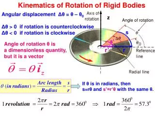
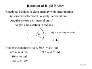
www.ekeeda.com Contact : 9029006464 Email : care@ekeeda.com ROTATION ABOUT FIXED AXIS In this motion all the particles forming the body travel along circular paths of different radii, around a common centre. This common point is known as centre of rotation. An axis perpendicular to the plane of the body and passing through the centre of rotation is known as the axis of rotation. Since the axis of rotation remains stationary or fixed, we call such motion as Rotation about Fixed Axis. Important Terms 1)Angular Position Let O, be the centre of rotation and z axis be the fixed axis of rotation. Let the x axis be the reference axis with respect to which we measure the position of the rotating body. Let us mark an arbitrary point P on the body. The angle measured in the anticlockwise direction which the line OP makes with the x axis would then be the angular position of the particle. As the body rotates and occupies position (2), the angular position of the body also changes and would have a new value of . Angular position is measured in units of radians (rad). It may also be measured in units of revolution or degree. These are related as 1 revolution = 2 rad = 360 For example, if the body’s initial angular position is 30 and it 0.5236 rad completes two revolutions, its new angular position would be, . 750 13.09 rad 3
www.ekeeda.com Contact : 9029006464 Email : care@ekeeda.com 2)Angular Displacement The change in angular position of the body during its motion is known as the angular displacement of the body. 1 , is the angular position of the body in position (1) and if this changes If 2 at position (2), the angular displacement of the body is, to = 2 1 3)Angular Velocity The rate of change of angular position with respect to time is the angular velocity of the rotating body. d dt ……. [13.2] The magnitude of angular velocity is denoted by notation (omega) and its direction acts along the axis of rotation, the sense being defined by right hand rule. i.e. for a body in the x-y plane rotating about a fixed axis parallel to the z axis in the anticlockwise direction, will have positive angular velocity. The same body, if its rotates in the clockwise direction will have negative angular velocity. Angular velocity is represented by curved arrow representing clockwise or anticlockwise sense. Units of angular velocity are rad/s, through other unit like revolutions per minute (rpm) is also commonly used. They are related as 2 60 1 rpm = rad/s 4)Angular Acceleration: The rate of change of angular velocity with respect to time is the angular acceleration of the rotating body. d dt The magnitude of angular acceleration is denoted by notation (alpha) and its direction acts along the axis of rotation. The sense of angular acceleration is same as the sense of angular velocity, if the angular velocity increases with time, and is opposite to the sense of angular velocity, if the angular velocity decreases with time. Angular acceleration is represented by curved arrow, representing clockwise or anticlockwise sense. Units of angular acceleration are rad/s2 ……. [13.3] 4
www.ekeeda.com Contact : 9029006464 Email : care@ekeeda.com Types of Rotation Motion about Fixed Axis Rotation about fixed axis can be classified under three categories, 1)Uniform Angular Velocity Motion: In this case of rotation motion the angular velocity of the rotating body remains constant during motion. For such motions, we use a simple relation relating , and t as .........[13.4] t 2)Uniform Angular Acceleration Motion: In this case of rotation motion, the angular velocity of the rotating body is not constant, but increases or decreases at a constant rate. If t we relate initial angular velocity final angular velocity angular acceleration angular displacement of the body time interval, then , , , and t as 0 0 = + a t …… [13.5 (a)] 0 2 …… [13.5 (b)] = t + ½ a t 0 2 2 …… [13.5 (c)] = + 2 a 0 3)Variable Angular Acceleration Motion: In this case of rotation motion the angular velocity changes during motion and the rate of change of angular velocity is variable. To solve problem on variable angular acceleration motion we make use of the basic differential equations discussed earlier. d dt d dt d dt From equations 13.2 and 13.3, we have d d .........[13.2] …… [13.2] …… [13.3] …… [13.6] 5
www.ekeeda.com Contact : 9029006464 Email : care@ekeeda.com Relation between Linear Velocity and Angular Velocity Consider a body rotating about a fixed axis passing through O. Let at the given instant, the angular velocity of the body be rad/s anticlockwise. All the particles on the rotating body will have the same angular velocity but different linear velocity. If vP is the linear velocity of a particle P and also rPO is the radial distance from P to O, then r v P PO The sense of vP would be consistent with the direction of . In general linear velocity v of any particle located at a radial distance r from the axis of rotation O is related to the angular velocity of the body by a relation. v r ………. [13.7] Relation between Linear Acceleration and Angular Acceleration Consider a body rotating about a fixed axis passing through O, having an angular velocity and angular acceleration , at the given instant as shown. We have studied in Chapter 9 that a particle in curvilinear motion, has acceleration 'a' which can be resolved into normal component an and tangential component at. Similarly if ap is the acceleration of particle P and if (an)p and (at)p are its components, then 6
www.ekeeda.com Contact : 9029006464 r ×ω r Email : care@ekeeda.com 2 2 v po a n p po 2 a po r n p d r dv dt dω dt a a po dt also po r po r t t p p In general the linear acceleration a of any particle located at a radial distance r from the axis of rotation O, has its components related to angular velocity and angular acceleration by the relation r 2 ………. [13.8 (a)] . na . ………. [13.8 (b)] ta r a 2 2 Also total linear acceleration a = a a n t 7
www.ekeeda.com Contact : 9029006464 Email : care@ekeeda.com Special case 1 of rotation motion: A block connected to s rotating pulley Consider a pulley of radius r, hinged at the centre and supporting a block by a string wound over it. The rotational motion of the pulley is related to translation motion of the block. This relation can be worked out. Let at a given instant, the pulley have an angular position of rad, angular velocity of rad/s and angular acceleration of rad/s2. Let xA, vA and aA be the corresponding position, velocity and acceleration respectively of the block A at this instant. Since the block translates, the string connecting it also translates. We find point P on the pu1ley is common to the rotating pulley and the translating block. Refer figure. If point P belongs to the pulley, its position, linear velocity and tangential acceleration is given by p v = r and ps = r r and a t p Relating these parameters to the motion of the connected block, we have r .……… [13.9 (a)] x s x A p A r ………. [13.9 (b)] v v v A p A a r and ………. [13.9 (c)] a a A t A p Equations 13.9 (a), (b) and (c) relate the motion of a block hanging from a rotating pulley. 8
www.ekeeda.com Contact : 9029006464 Email : care@ekeeda.com Special case 2 of rotation motion: A pulley coupled to another pulley and they rotate without slip Consider a pulley A of radius rA, be coupled to another pulley B of radius rB, and the two rotate without slip. The rotational motion of pulley A is related to the rotational motion of pulley B. This relation can be worked out. Let at a given instant, pulley A have an angular rad, angular velocity of position of A A rad / s2. rad/s and angular acceleration of A , and be the corresponding angular position, angular velocity Let B B B and angular acceleration of pulley B at this instant. Since the pulley A rotates, it causes pulley B to also rotate. We find point P is a common point to the two pulleys. If point P belongs to pulley A, its position, linear velocity and tangential acceleration is given by S = r θ v = r ω (a ) = r α and and P A A P A A t P A A Similarly point P also belongs to pulley B, therefore if the above parameters are related to the pulley B, we have s = r θ = r θ ………. (a) P A A B B v = r ω = r ω ………. (b) P A A B B (a ) = r α = r α Equation (a), (b) and (c) relate the motions of two pulleys or gears engaged ………. (c) t P A A B B with one another. 9
www.ekeeda.com Contact : 9029006464 Email : care@ekeeda.com EXERCISE 1 1.The tub of a washing machine is rotating at 60 rad/sec when the power is switched off. The tub makes 49 revolutions before coming to rest. Determine the constant angular deceleration of the tub and the time it takes to come to a halt. 2.P2. A wheel rotating about a fixed axis at 15 rpm is uniformly accelerated for 60 sec during which it makes 30 revolutions. Find a)angular velocity in rpm at the end of the interval. b)time required to attain a speed of 30 rpm. . 3.A point on the rim of a flywheel has a peripheral speed of 6 m/s at an instant which is decreasing at a rate of 30 m/s2. If the magnitude of the total acceleration of the point at this instant is 50 m/s2, find the diameter of the flywheel. 4.A 1 m diameter flywheel has an initial clockwise angular velocity of 5 rad/s and a constant angular acceleration of 1.5 rad/s2. Determine the number of revolutions it must make and the time required to acquire a clockwise angular velocity of 30 rad/s. Also find the magnitude of linear velocity and linear acceleration of a point on the rim of the flywheel at t = 0. 5.A windmill fan during a certain interval of time has an angular acceleration defined by a relation α = 18 e - 0-3 t rad/s2. The blades of the fan describes a circle of radius 2.5 m. If at t = 0, ω = 0, determine at t = 5 sec a)angular velocity of the fan b)revolutions undergone by the fan. c)Speed of the tip of fan blade. 6.A concrete mixer drum A is being rotated by two gears B and C. If the concrete mixer is designed to attain a speed of 6 rad/s uniformly in 30 sec, starting from rest and then maintain this speed, determine d)the number of revolutions undergone by the drum at t = 300 sec e)the angular acceleration to be developed in the driving gears. f)velocity of concrete particles touching the inner wall of the drum during uniform rotation motion of the drum 10
www.ekeeda.com Contact : 9029006464 Email : care@ekeeda.com 7.The variation of angular speed with time of a fan is shown. Find number of revolutions undergone by the fan during a 10 minutes interval. a)the angular acceleration and angular deceleration during this time interval. b)the magnitude of velocity and acceleration of a point on the tip of the fan at t = 9 minutes, knowing that the fan described a circle of 1200 mm diameter. 8.The angular displacement of the rotating wheel is defined by the relation θ = 1/4 t3 + 2 t2 + 18 rad. Determine the angular velocity and angular acceleration of the wheel at t = 5 sec. 9.The angular acceleration of a rotating rod is given by the relation α = 9.81 cos θ-2.22 rad/s2. The rod starts from rest at θ = 0. Find g)the angular velocity and angular acceleration of the rod at 0 = 30°. h)the maximum angular velocity and the corresponding angle 0. 10.A belt is wrapped over two pulleys transmitting the motion without slipping. If the angular velocity of the driver pulley A is increased uniformly from 2 rad/s to 16 rad/s in 4 sec, determine i)the acceleration of the straight position of the belt j)the magnitude of total acceleration of a point on the rim of pulley B at t = 4 sec. k)the number of revolutions turned by the two pulleys at t = 4 sec. 11.Find the angular velocity in rad/s for l)the second hand, the minute hand and hour hand of a watch, m)the earth about its own axis. 11
www.ekeeda.com Contact : 9029006464 Email : care@ekeeda.com GENERAL PLANE MOTION Translation motion and rotation about fixed axis motion are plane motions since the motion of the body can be analysed by taking a representative slab or a plane of the body. They may also be referred to as a Two Dimensional Motion. Any plane motion which does not fall under the category of rotation about fixed axis or translation motion can be put under the category of general plane motion. In fact a general plane motion is a combination of translation motion and rotation motion. Three examples of body performing general plane motion are shown below. In Fig. (a), Two blocks A and B travel is fixed slot performing translation motion. The blocks are pin-connected by a link AB. The link AB moves from position (1) to position (2) performing general plane motion. We observe that the link AB rotates, but not about a fixed axis. Thus the centre of rotation of the link AB performing general plane motion keeps on moving at every instant. In Fig. (b), rod AB, rod BC and block C, form a pin-connected mechanism. The rod AB performs rotation motion about fixed axis at A. Piston C is free to perform translation motion in the fixed slot. It is the rod BC which neither performs pure translation or pure rotation motion. It is therefore said to perform general plane motion. The centre of rotation of rod BC keeps on changing as it performs general plane motion. 12
www.ekeeda.com Contact : 9029006464 Email : care@ekeeda.com In Fig. (c), a wheel rolls without slip on the ground. The rolling wheel rotates as well as translates. It therefore performs general plane motion. In general any-body which rolls without slip performs general plane motion. Though G.P. bodies don’t actually translate and then rotate in succession, but the motion can be duplicated by first translating the body and then rotating it. General Plane Motion = Translation Motion + Rotation Motion Consider a body which has moved from position (1) to position (2) performing G.P. motion. Refer Fig. Let P and Q be two arbitrary points chosen on it. We may duplicate the motion by first translating the body to its position (2), i.e. segment PQ maintains its orientation and remains parallel. Now we can rotate the body about P to get the true orientation of the body. Hence G.P. Motion is said to be a sum of Translation Motion and Rotation Motion. 13
www.ekeeda.com Contact : 9029006464 Email : care@ekeeda.com RELATIVE VELOCITY METHOD We know that a G.P. Motion is a sum of translation and rotation motion. To find the angular velocity of a body performing G.P. Motion, we may use the relative Velocity Method, which is one of the methods for analysing G.P. motion. To understand this method we note down the required steps and simultaneously take up an example and apply the procedure. Consider a rod AB pin-connected to pistons A and B which move in fixed slots as shown. Let piston B have a known velocity vB to the right. Let us learn to find angular velocity of the G.P. body AB. AB Step 1.Locate a point on the G.P. body whose magnitude and direction of velocity is known. Such a point is referred to as the reference point and the known velocity is referred to as the translating velocity. In our example, the velocity of point B i.e. vB is known. Hence B is the reference point and vB is the translating velocity. Step 2.Locate another point on the G.P body whose direction of velocity is known. Such a point is referred to as translation point. In our example, the direction of velocity of point A is known, since it is constrained to move in the vertical slot. Point A is therefore the translation point. Step 3.Translate the body with the translating velocity and then rotate it about the reference point with the angular velocity of the G.P body. In our example, the bar is translated with translating velocity vB and then rotated about reference point B with angular velocity Step 4.Write the relation for the relative linear velocity of translation point. In our example, we write the relative linear velocity of translation point A as A/B AB AB V = r + . AB …… (1) 14
www.ekeeda.com Contact : 9029006464 Email : care@ekeeda.com Step 5.Write the relation for the absolute velocity of the translation point. Simultaneously draw the vector diagram for the same. Obtain the relative velocity of the translation point and hence obtain the angular velocity of the G.P body. In our example, V = V + V ….. (2) A B A/B From relation (2), can be found out, which in turn when V A B / substituted in relation (1) gives the angular velocity . AB Instantaneous Centre Method Instantaneous Centre is defined as the point about which the G.P. body rotates at the given instant. This point keeps on changing as the G.P. body performs its motion. The locus of the instantaneous centres during the motion is known as centroid. Instantaneous Centre may be denoted by letter I. Let us understand the Instantaneous Centre Method to find the angular velocity of a G.P body. Let us work with the earlier example we took in article 13.5.1 Given- vB i.e. velocity of block B To find - Angular velocity of rod AB at given instant Step 1.Locate a point on the G.P body whose magnitude, direction and sense of velocity is known and another point whose direction of velocity is known. Mark the direction of velocity (Dov) of these two points. In our example, the magnitude and Dov of point B (DovB) is known and also Dov of point A is known (DovA) 15
www.ekeeda.com Contact : 9029006464 Email : care@ekeeda.com Step 2.Draw perpendiculars to the direction of velocities (Dov) and extend them to intersect at a point. Call this point as I. Step 3.Point I i.e. the instantaneous centre, is the centre of rotation of the G.P body at the given instant. Now treating the G.P body as a rotating body about I, and using v = r ω relation, the angular velocity of the G.P body can be found out. In our example, the radial length rBI can be found out by geometry of ABI. Next using vB = rBI × ωAB The angular velocity ωAB can be found out Also now knowing ωAB , velocity of block A can be found out, using vA - rAI × ωAB 16
www.ekeeda.com Contact : 9029006464 Email : care@ekeeda.com ROTATION ABOUT FIXED POINT In this type of rigid body motion, the body rotates about a fixed point, but the axis of rotation passing through the fixed point is not stationary as its direction keeps on changing. Such motion is a threedimensional motion. Example of this type of motion is of a top rotating about the pivot at O. The axis of rotation is not fixed but changes its direction as the top rotates about fixed pivot point O. Refer Fig. Another example of rotation about a fixed point is of the motion of a boom which is ball and socket supported at a point O on the crane. Fig. 13.15 shows the boom of a crane being raised up by rotation about the z axis, and at the same time the crane itself rotates about the y axis to position the boom over its target. GENERAL MOTION Any other motion of the rigid bodies which do not fit in any of the above four types of rigid body motion, may be classified as a General Motion. Motion analysis of a rigid body having Rotation Motion about a Fixed Point of General Motion of a rigid body are beyond the scope of this book. 17
www.ekeeda.com Contact : 9029006464 Email : care@ekeeda.com EXERCISE 2 1.The rod ABC is guided by two blocks A and B which move in channels as shown. At the given instant, velocity of block A is 5 m/s downwards. Determine a)the angular velocity of rod ABC b)velocities of block B and end C of rod. 2.A rod AB 26 m long leans against a vertical wall. The end ‘A’ on the floor is drawn away from the wall at a rate of 24 m/s. When the end ‘A’ of the rod is 10 m from the wall, determine the velocity of the end ‘B’ sliding down vertically and the angular velocity of the rod AB. 3.A slider crank mechanism is shown in figure. The crank OA rotates anticlockwise at 100 rad/s. Find the angular velocity of rod AB and the velocity of slider at B. 4.In a slider crank mechanism as shown in figure the crank is rotating at as constant speed of 120 rev/min. The connecting rod is 600 mm long and the crank is 100 mm long. For an angle of 30°, determine the absolute velocity of the crosshead P. 18
www.ekeeda.com Contact : 9029006464 Email : care@ekeeda.com 5.Block ‘D’ shown in figure moves with a speed of 3 m/s. Determine the angular velocities of links BD and AB and the velocity of point B at the instant shown. Use method of instantaneous centre of zero velocity. 6.For the position shown, the angular velocity of bar AB is 10 rad/s anticlockwise. Determine the angular velocities of bars BC and CD. 7.Rod BCD is pinned to rod AB at B and has a slider at C which slides freely in the vertical slot. At the instant shown, the angular velocity of rod AB is 4 rad/s clockwise. Determine a)angular velocity of rod BD b)velocity of slider C c)velocity of end D of the rod BD 8.A rod AB 1.8 m long, slides against an inclined plane and a horizontal floor. The end A has a velocity of 5 m/s to the right. Determine the angular velocity of the rod and the magnitude of velocity of end B and the midpoint M of the rod for the instant shown. 19
www.ekeeda.com Contact : 9029006464 Email : care@ekeeda.com 9.A slender beam AB of length 3 m which remains always in a same vertical plane as its ends A and B are constrained to remain in contact with a horizontal floor and a vertical wall as shown. Determine the velocity at point B using instantaneous centre method. 10.A wheel of radius 0.75 m rolls without slipping on a horizontal surface to the right. Determine the velocities of the points P and Q shown in figure when the velocity of centre of the wheel is 10 m/s towards right. 11.One end of rod AB is pinned to the cylinder of diameter 0.5 m while the other end slides vertically up the wall with a uniform speed of 2 m/s. For the instant, when the end A is vertically over the centre of the cylinder, find the angular velocity of the cylinder, assuming it to roll without slip. 12.A flanged wheel rolls to the left on a horizontal rail as shown. The velocity of the wheel’s centre is 4 m/s. Find velocities of points D, E, F and H on the wheel. 20
www.ekeeda.com Contact : 9029006464 Email : care@ekeeda.com 13.Rod AB has a constant angular velocity of 50 rpm clockwise. For the given position of the mechanism, find the angular velocity of rods BC and CD. 14.If the link CD is rotating at 5 rad/sec anticlockwise, determine the angular velocity of link AB at the instant shown. 15.Blocks A, B and C slide in fixed slots as shown. The blocks form interconnected by pin-connected links AB and BC. L (AB) = 400 mm and L (BC) = 600 mm. At the given instant, block A has a velocity of 0.15 m/s downwards. Determine the velocities of blocks B and C for the given instant. 16.In the mechanism shown the angular a mechanism, being velocity of link AB is 5 rad/s anticlockwise. At the instant shown, determine the angular velocity of link BC, velocity of piston C and velocity of midpoint M of link BC. 17.In the engine system shown, the crank AB has a constant clockwise angular velocity of 2000 rpm. For the crank position shown determine the angular velocity of connecting rod BD and velocity of the piston D. Use ICR method. 21
www.ekeeda.com Contact : 9029006464 Email : care@ekeeda.com 18.Locate the instantaneous center of rotation for the link ABC and determine velocity of points B & C. Angular velocity of rod OA is 15 rad/sec counter clock wise. Length of OA is 200 mm, AB is 400 mm and BC is 150 mm. 19.The bar BC of the linkage shown has an angular velocity of 3 rad /sec clockwise at the instant shown. Determine the angular velocity of bar AB and linear velocity of point P on the bar BC. 22
www.ekeeda.com Contact : 9029006464 Email : care@ekeeda.com EXERCISE 3 Theory Questions Q.1.Classify types of motion for rigid body with suitable examples. Q.2.Explain the characteristics of a Translating Body. Q.3.For a rotating body explain in brief the terms 1)Angular Position, 2)Angular Displacement 3)Angular Velocity 4)Angular Acceleration. Q.4.What sire the different types of Rotation Motion about fixed axis and list the corresponding equations applicable? Q.5.Explain Instantaneous Centre of Rotation. Q.6.Write a short note on General Plane Motion. UNIVERSITY QUESTIONS 1.For the link and slider mechanism shown in figure, locate the instantaneous centre of rotation of link AB. Also find the angular velocity of link ‘OA’. Take velocity of slider at B = 2500mm/sec. (10 Marks) 2.‘C’ is a uniform cylinder to which a rod ‘AB’ is pinned at ‘A’ and the other end of the rod ‘B’ is moving along a vertical wall as shown in fig. If the end ‘B’ of the rod is moving upward along the wall at a speed of 3.3 m/s find the angular velocity of the cylinder assuming that it is rolling without slipping. (6 Marks) 23
www.ekeeda.com Contact : 9029006464 Email : care@ekeeda.com 3.Find the forces in members BD, BE and CE by method of section only for the truss shown in the fig. Also find the forces in other members by method of joints. (8 Marks) 4.Collar B moves up with constant velocity V =2m/s.Rod AB is pinned at B. B Find out angular velocity of AB and velocity of A. (6 Marks) 5.Fig. shows the crank and connecting rod mechanism. The crank AB rotates with an angular velocity of 2 rad/sec in clockwise direction. Determine the angular velocity of Connecting Rod BC and the velocity of piston C using ICR method. AB = 0.3 m and CD = 0.8 m (6 Marks) 6.In the mechanism shown the angular velocity of link AB is 5 rad/sec anticlockwise. At the instant shown, determine the angular velocity of link BC and velocity of piston C. (6 Marks) 24
www.ekeeda.com Contact : 9029006464 Email : care@ekeeda.com 7.Due to slipping, points A and B on the rim of the disk have the velocities as shown in figure. Determine the velocities of the centre point C and point D on the rim at this instant. Take radius of disc 0.24 m (6 Marks) 25