Software Solutions for NVG ENVG Integration
Software Solutions for NVG ENVG Integration. Keywords SWIR Imaging Night Vision Sensor Fusion Sub Pixel Image Analysis September 22th 2010. Robotics and Computer Vision System Integration Guy Martin BEng MScA guyj.martin@gmail.com Marie-Josée Perreault BBA mj.perreault@gmail.com.


Software Solutions for NVG ENVG Integration
E N D
Presentation Transcript
Software Solutions for NVG ENVG Integration Keywords SWIR Imaging Night Vision Sensor Fusion Sub Pixel Image Analysis September 22th 2010 Robotics and Computer Vision System Integration Guy Martin BEng MScA guyj.martin@gmail.com Marie-JoséePerreault BBA mj.perreault@gmail.com
No automation system is more accurate than its instrument… All advanced imagery techniques require a pinhole ‘errorless’ camera image, where geometric and chromatic distortion are removed, and without bias in the image center. In NVG and ENVG applications, it enables sub pixel edge extraction, sensor fusion, and added lossless video compression. We discovered systematic biases in the modeling and calibration procedure for digital cameras Our testing uses low accuracy 1024x768 and 640x480 cameras, a typical resolution for SWIR imaging. We retrieve the camera focal distance to an unmatched 10e-10 mm… We demonstrated in June 2009 that a software image correction approach could gain 8:1 higher image accuracy 4:1 faster computation time 30% added lossless video compression It provides us with multiple integration trade offs between, computation speed, cost, accuracy, video compression, lens selection,… Our software platform is source code compatible and opened...
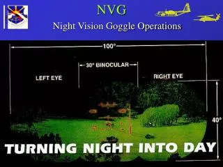
Impact: Image Fusion and Night Vision • The problem: • Use wide angle lenses to increase the camera angle of view • Compensate SWIR (900 – 1700 nm)cameras’ low 640x480 resolution • Modify the ROIC analog circuit for uncooled InGaAs arrays to allow more amplification in low light conditions • Allow sensor fusion between SWIR Color synthetic images • Constraint: The image may not lag by more than 250 msec • Our answer: High accuracy camera calibration and software image correction combined with sub pixel edge analysis • ROIC analog filter design
Making sub pixel information significant As the wavelength increases, f increases, and the image grows bigger. Measuring an object across the spectrum creates a size bias… Lens distortion creates the biggest error in software imaging, and it amplifies getting away from the image center As soon as you increase the lens angle of view… Geometric distortion curves straight lines and shears objects’ squareness Chromatic distortion splits light with respect to wavelength, whatever the spectrum Both prevent sub pixel edge analysis and have to be removed from the image. Some compensation comes from lens design, the remainder has to be corrected through software
Overall Performance Is an Integration Trade Off Between • Lens-filter selection and design • Read out analogue circuit behaviour with regards to pixel gain variation and noise • Camera embedded software • Computer software for advanced image treatment Hardware design impacts on future software image enhancements Software image correction is dependant on accurate camera calibration
Camera Calibration is knowing how an image prints through the lens on the camera surface For a fixed f lens The Camera Model has three parts - External Model - Lens Model - Internal Model 5 Internal Parameters The camera pixel being square, a should equal b, with skew parameter s close to zero Shawn Becker’s Lens Distortion Model (MIT & NASA) x' = x + x*(K1*r^2 + K2*r^4 + K3*r^6) + P1*(r^2 + 2*x^2) + 2*P2*x*y y' = y + y*(K1*r^2 + K2*r^4 + K3*r^6) + P2*(r^2 + 2*y^2) + 2*P1*x*y We removed ¾ of the terms to gain accuracy!...
Calibration Performance Criteria We have to compensate for wavelength-colour variations in order to find the true edge at sub pixel level
Calibration Results Leftmost data set gives results for a model equivalent to the ones generally used, and rightmost, our most accurate result using the same experimental data on our own model. 6 External Parameters 5 internal parameters 2 geometric distortion parameters The camera pixel being square, a should equal b=f, with skew parameter s close to zero Left model shows error on f 10e-03mm Right model shows error on f 10e-10mm , corrected a systematic error on image center by as much as 2 pixels, and an underestimation of distortion parameters
Lens Model: Chromatic Distortion Amplified 50 times, our chromatic distortion model is purely radial and has a single image center for all three color channels RGB. We remove a ±½ pixel error on edge location. Top left - red distortion, Bottom left - blue distortion Note that they don’t peek at the same distance from the image center Testing on a 1024x768 camera
Lens Distortion Correction This image was taken by a 640x480 Bayer pattern color camera using a f=4mm lens, calibrated in lab from our algorithms and setup.
Sub pixel edge analysis Working from a 3x3 footprint on low definition cameras, edges look blockish. Devernay’s non maxima suppression technique (INRIA 1995) works for horizontal or vertical straight lines only. It had to be adapted for corner detection and corrected for curvature end edge orientation bias
Sub pixel edge analysis Once corrected, it becomes a good all purpose edge detection technique for highly pixelized and blurred images
Sensor Fusion A computer generated image has exact f and perspective Fusion of SWIR and Color images require exactly same f and exact removal of lens distortion Fusion to synthetic image is basic to augmented reality Color camera should have a 1024x768 resolution Fusion with a 640x480 SWIR Eventually use a zooming lens on the color camera… Computation speed then becomes an issue Synthetic vision with Vision Amplification should appear in civilian airline transportation around year 2018
Annex A: Spectrum and Lens Distortion SWIR wavelengths will focus further right along the lens axis… A CCD will see lower SWIR wavelengths Split up remaining SWIR spectrum to give spectral resolution
Annex B: Bayer Pattern Recovery The most accurate Bayer pattern interpolation schemes use edge sensing to recover missing RGB information. Missing values are interpolated using neighbouring pixel information. In a two step process, we first compute the missing G pixel values on B and R pixels Ex.: On red pixel R13, the missing G13 value is computed as (G12+G14)/2 if the edge is horizontal (R13>(R3+R23)/2) (G8+G18)/2 if the edge is vertical (R13>(R11+R15)/2) (G12+G8+G14+G18)/4 otherwise In step two, we compute missing B and R values using known G But the lens introduces errors in the image, geometric and chromatic distortion, curving edges, and ‘color shifting’ edge location as we scan from B to G to R pixels. The Bayer pattern recovery requires adapting for geometric and chromatic distortion, while in monochrome imaging, accuracy is dependant on optical spectrum spread. A BAYER COLOR CAMERA IS A SPECTRUM ANALYZER USE THE SAME SCHEME ON THE SWIR SPECTRUM ?!…