Properties of Multilayer Optics
130 likes | 387 Vues
Properties of Multilayer Optics. An Investigation of Methods of Polarization Analysis for the ICS Experiment at UCLA 8/4/04 Oliver Williams. Outline. Purpose Review of Polarization/Analysis in Visible EUV/Soft x-ray Behavior in Materials Basics of Multilayer Optics

Properties of Multilayer Optics
E N D
Presentation Transcript
Properties of Multilayer Optics An Investigation of Methods of Polarization Analysis for the ICS Experiment at UCLA 8/4/04 Oliver Williams
Outline • Purpose • Review of Polarization/Analysis in Visible • EUV/Soft x-ray Behavior in Materials • Basics of Multilayer Optics • ML Optics as Polarizers/Phase Retarders • Summary
Purpose • Beam electrons scattering off CO2 laser photons (~0.12 eV) expected to produce ~110 eV photons • Scattered photons assume polarization state of laser photons = circular for ICS experiment • Require analyzer capable of determining degree of polarization of soft x-rays
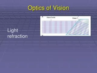
Review of Polarization • A preferential orientation of the electric field along a single axis perpendicular to the direction of propagation= Linearly polarized • When the horizontal and vertical components of electric field are 90 degrees out of phase= Circularly polarized • At a boundary of different index of refraction (e.g. air-glass): Horizontal = s-component (E-field perpendicular to plane of incidence) Vertical = p-component (E-field parallel to plane of incidence) • Brewster’s Angle: Angle at which the s-component of the E-field is completely reflected while the p-component is completely absorbed or transmitted; dependent on the index of refraction of material.
Some Methods of Polarization/Analysis • Dichroic/Wire grid polarizers – Linear • Brewster’s angle based – Linear • Birefringence (crystals) – Linear & Circular • 1/4 wave plates – Circular Of particular interest to the ICS experiment are analyzers based on quarter wave plates due to their ability to retard (or advance) the relative phases of the s and p components of the electric field by 90 degrees (ideally). The well-known method of using a ¼ wave plate followed by a linear polarizer as an analyzer can be used to determine the degree of circular polarization of the scattered photons. However…
EUV/Soft X-ray Behavior in Materials • The real part of the refractive index (nr) of materials seen by light in the EUV/SXR (>30 eV approx.) approaches unity as the energy increases. The complex refractive index is, where δ is the decrement of the real part of the refractive index and β is the absorption index with both typically very small (<10-3) for this energy. • This makes conventional optics almost useless, except at grazing/glancing angles (θ<5 deg), as the amplitude reflectivity of a surface for EUV/SXR ranges 1/30 to 1/100.
Basics of Multilayer Optics • If the reflections of 30-100 surfaces can be arranged such that their phases interfere constructively at the top surface, a total reflectivity close to one can be achieved. • Bragg condition: Light reflecting off many surfaces will be strongly dependent on the distance between reflection layers (d) and the angle of incidence (θ) as the total distance traveled must be an integer number (m) of wavelengths (λ) to constructively interfere and is given by the equation, • The dependence of the reflectivity on the wavelength of light makes ML optics inherently good filters
ML Optics as Linear Polarizers • Because the index of refraction for EUV/SXR light is close to one, Brewster’s angle is near 45 degrees. • Adjusting the spacing between layers (d) in the Bragg equation one can place this Bragg reflection peak also near 45 degrees • This causes the ML optic to be highly reflective (due to the multilayer reflections) and especially to the s-component since the angle of maximum reflection is at Brewster’s angle • This makes ML optics almost perfect linear polarizers as the relative reflection (transmission) between the s and p components is very large (small). • http://www-cxro.lbl.gov/optical_constants/multi2.html
ML Optics as Phase Retarders • There already exist modest phase shifts between the s and p components at dielectric/vacuum interfaces at certain angles of incidence, however because the reflectivity is so low it is inefficient to be used as a retarder. • Graphs to the right show the reflectance of the s and p components of 90 eV photons on a Molybdenum mirror as a function of incidence angle as well as the (normalized) relative phase shift, Δφ. • Adding multilayers changes the optical properties around Bragg peak, especially.
Reflection Retarders • As seen from the plots, phase retardation based on reflection can be quite effective, producing Δφ≈45 degrees. • Because of the necessity of operating near 45 degrees for decent phase shifts, the reflectivity of the p-component is quite low (≤0.1), which is extended to ≤0.01(two reflections) if it is to function as a ¼ wave plate. • Besides the inefficiency, the introduction of one more optical element to align, especially under vacuum and only receiving a signal every few minutes (for us), makes reflection retarders difficult to use.
Transmission Retarders • Essentially same fabrication process as reflection type except necessity of removing substrate by etching gives higher surface roughness. • However, the transmission retarder is able to achieve Δφ≈90 degrees between s and p on only one pass with about the same efficiency as one reflection. • This is made possible by the modulation of the electric field between the low and high absorption regions of the ML.
Transmission vs. Reflection • Upon strong reflection off a layer a standing wave is formed which effectively changes the refractive index felt by the total field. • If the Bragg peak is placed near Brewster’s angle, only the s-component feels this electric field modulation and change in refractive index which causes a phase shift with respect to the p-component. • The effect of this modulation in the transmission case (top graph) is compared to reflection and it can be seen in the plots that the normalized phases of the s and p components in transmission more strongly “slip” past each other at certain angles than for reflection. • Because this change in phase is so heavily dependent on strong E-field modulation, and hence strong reflection, poorly fabricated transmission ML’s are much less forgiving in phase shifts than reflection ML’s.
Summary • Multilayer optics are excellent small bandwidth filters • Reflective linear polarizers based on ML’s are very effective in the EUV/SXR region • ¼ wave plates based on transmissive multilayers have shown to be more efficient and practical than the reflection type • Sensitivity to imperfections make the fabrication of transmission ML’s more difficult and (most likely) more expensive than reflection ML’s • An x-ray detector in combination with a transmission retarder and reflection analyzer (polarizer) mounted on vacuum compatible motorized rotation stages could be used to verify the circular polarization of the ICS photons at Neptune