Download

1 / 87
1.22k likes | 2.09k Vues
Fundamentals of Optics. Jiun-You Lin Department of Mechatronics Engineering, National Changhua University of Education. Historically, optical theory developed roughly in the following : sequence: (1) ray optics (2) wave optics (3) electromagnetic optics (4) quantum optics

E N D
Fundamentals of Optics Jiun-You Lin Department of Mechatronics Engineering, National Changhua University of Education
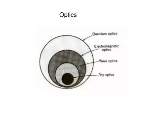
Historically, optical theory developed roughly in the following : sequence: (1) ray optics (2) wave optics (3) electromagnetic optics (4) quantum optics • The theory of quantum optics provides an explanation of virtually all optical phenomena. The theory of electromagnetic optics provides the most complete treatment of light within the confines of classicaloptics(electromagnetic optics, wave optics, ray optics) • Wave optics is a scalar approximation of electromagnetic optics. Ray optics is the limit of wave optics when the wavelength is very short.
Outline • Wave Nature of Light • Polarization and Modulation • of Light
Wave Nature of Light • Light Waves in a Homogeneous Medium A. Plane Electromagnetic Wave B. Maxwell’s Wave Equation and Diverging Waves • Refractive Index • Magnetic Field, Irradiance, and Poynting Vector • Snell’s Law and Total Internal Reflection
Fresnel’s Equations A. Amplitude Reflection and Transmission Coefficients B. Reflectance and Transmittance • Interference Principles A.Interference of Two Waves B. Interferometer • Diffraction Principles A. Diffraction B. Fraunhofer Diffraction C. Diffraction grating
Light Waves in a Homogeneous Medium • Ultraviolet • 10nm~390nm • Visible • 390nm~760nm • Infrared • 760nm~1mm Optical frequencies and wavelengths
E x Direction of Propagation k x z z y B y An electromagnetic wave is a travelling wave which has time varying electric and magnetic fields which are perpendicular to each other and the direction of propagation, z. A. Plane Electromagnetic Wave
A sinusoidal wave (1) Ex : the electric field at position z at time t Eo : the amplitude of the wave : the angular frequency k=2/: the propagation constant o : phase constant (t-kz+o) : the phase of the wave
E and B have constant phase in this xy plane; a wavefront z E E k Propagation B E x z A plane EM wave travelling along z , has the same E (or B ) at any point in a y x given xy plane. All electric field vectors in a given xy plane are therefore in phase. The xy planes are of infinite extent in the x and y directions. A monochromatic plane wave
Eq. (1) can be rewritten as Ex(z,t)=Re[Eoexp(jo)expj(t-kz)] =Re [Ecexpj(t-kz)] (2) where Ec= Eoexp(jo) complex number that represents the amplitude of the wave and includes the constant phase information o
y Direction of propagation k E ( r , ) t r q r z O A travelling plane EM wave along a direction k .
E(r,t)=Eocos(t-kr+o) (3) where kr=kr =kxx+kyy+kzz The relationship between time and space for a given phase, for example, that corresponding to a maximum field, according to Eq. (1): =t-kz+o=constant (4) The phase velocity v=dz/dt=/k= (5)
Wave fronts (constant phase surfaces) Wave fronts Wave fronts k P l l E r k l P O z A perfect plane wave A perfect spherical wave A divergent beam (a) (b) (c) Examples of possible EM waves B. Maxell’s Wave Equation and Diverging Waves
There are many types of possible EM waves: • Plane wave: the plane wave has no divergence • Spherical wave: wavefronts are spheres and k • vectors diverge out • E=(A/r)cos(t-kz) • where A is a constant • Divergent beam: the wavefront are slowly bent • away thereby spreading the wave (6)
y Wave fronts (b) x 2 w z O Beam axis o Intensity (c) q Gaussian (a) r 2 w (a) Wavefronts of a Gaussian light beam. (b) Light intensity across beam cross section. (c) Light irradiance (intensity) vs. radial distance r from beam axis ( z ). Ex. The Output from a laser (Gaussian beam)
2w: the beam diameter at any point z • w2: the cross sectional area at z point contains • 85% of the beam power • 2wo: the beam diameter at point O = the waist • of the beam =the spot size • wo: the waist radius • : divergence angle • 2=4/(2o) (7)
In an isotropic and linear dielectric medium, these fields must obey Maxwell’s EM wave equation, (8) o : the absolute permeability o : the absolute permittivity r : the relative permittivity of the medium
Refractive Index For an EM wave traveling in a nonmagnetic dielectric medium of relative permittivity r, the phase velocity v is given by v= 1/(roo)1/2 (9) For an EM wave traveling in free space, r=1, the phase velocity v is given by vvacuum= 1/(oo)1/2=c=3108ms-1 (10) The refractive index n of the medium: n=c/v= (r)1/2 (11)
In free space, the wavenumber: (12) k=2/ In an isotropic medium, the wavenumber: kmedium=nk medium=/n (13a) (13b) Light propagates more slowly in a denser medium that has a higher refractive index, and the frequency remains the same.
D v t z E Area A k Propagation direction B k A plane EM wave travelling along crosses an area A at right angles to the D D direction of propagation. In time t , the energy in the cylindrical volume A v t (shown dashed) flows through A . Magnetic Field, Irradiance and Poynting Vector
Fields in an EM wave Ex=vBy=(c/n)By (14) Energy densities in an EM wave (1/2)ro Ex2= (1/2 o) By2 (15) The EM power flow per unit area S= Energy flow per unit time per unit area =(Avt) (ro Ex2)/(At)=v ro Ex2 = v 2ro ExBy (16)
Poynting Vector S= v 2roEB Irradiance |S|= v 2ro|EB| (17) The energy flow per unit time per unit area in a direction determined by EB (18)
Snell’s Law and Total Internal Reflection A t A l t k t Refracted Light B t A y q q t t n 2 A z B n O 1 q q q q i i r r A B k i l l k r A B i r A Reflected Light Incident Light B r i A light wave travelling in a medium with a greater refractive index ( n > n ) suffers 1 2 reflection and refraction at the boundary.
Ai and Biare in phase • Ar and Br must still be be in phase • BB=AA=v1t • AB=v1t/sin i =v1t/sinr ir • Ai and Biare in phase • A and B must still be be in phase • BB=v1t=ct/n1 ; AA=v2t =ct/n2 • AB= BB /sin i = AA /sin t
AB= BB /sin i = AA /sin t = v1t/sin i = v2t/sin t Snell’s law: sin i /sint=v1/v2=n2/n1 (19)
Transmitted (refracted) light k t q n Evanescent wave t 2 n > n 1 2 q q q > q q q k k i c c i i c i r TIR Incident Reflected light light ( c ) ( a ) ( b ) Light wave travelling in a more dense medium strikes a less dense medium. Depending on q the incidence angle with respect to , which is determined by the ratio of the refractive c q q q q q indices, the wave may be transmitted (refracted) or reflected. (a) < (b) = (c) i c i c i q > and total internal reflection (TIR). c When n1>n2 and the refraction angle t reaches 90 Critical angle: sin c=n2/ n1 (20)
E , t // Transmitted wave y n k q =90 2 t t q t E Evanescent wave E t , ^ t, ^ z k n > n x into paper i q q E r q q i 1 2 E r i i , // E E i, // r , r , ^ ^ E E E i , k ^ i i , , ^ ^ r E E r ,// r ,// Reflected Incident Reflected Incident wave wave wave wave q q (a) < then some of the wave q q (b) > then the incident wave i c i c is transmitted into the less dense suffers total internal reflection. medium. Some of the wave is However, there is an evanescent reflected. wave at the surface of the medium. Light wave travelling in a more dense medium strikes a less dense medium. The plane of incidence is the plane of the paper and is perpendicular to the flat interface between the two media. The electric field is normal to the direction of propagation . It can be resolved ^ into perpendicular ( ) and parallel (//) components Fresnel’s Equations • Amplitude Reflection and Transmission Coefficients
Ei, Er ,and Et: transverse electric field (TE) • Ei//, Er// ,and Et//: transverse magnetic field (TM) • Incident wave, reflected wave, and transmitted wave • Ei=Eioexpj(t-kir) • Er=Eroexpj(t-krr) • Et=Etoexpj(t-ktr) (21a) (21b) (21c)
r=Ero, /Eio,= t=Eto, /Eio,=1+ r r//=Ero,// /Eio,//= t//=Eto,// /Eio,//=(1/n)(1+ r//) According to Maxwell’s EM wave equations and Boundary conditions Reflection and transmission coefficients for E and E// (22a) (22b) (22c) (22d) where n=n2/n1
Magnitude of reflection coefficients Phase changes in degrees q c TIR 1 180 ( a ) ( b ) 0.9 120 0.8 f 0.7 ^ 60 q 0.6 p 0.5 0 q 0.4 r c | | - 60 ^ f 0.3 // q 0.2 p r | | -1 20 // 0.1 0 -1 80 0 10 20 30 40 50 60 70 80 90 0 10 20 30 40 50 60 70 80 90 q Incidence angle, q Incidence angle, i i r r Internal reflection: (a) Magnitude of the reflection coefficients and ^ // q vs. angle of incidence for n = 1.44 and n = 1.00. The critical angle is 1 2 i f f 44? (b) The corresponding phase changes and vs. incidence angle. // ^
Normal incidence: • r//=r= (n1n2)/( n1 +n2) • Polarization angle =Brewser’s angle: • r//=0 tan p=n2/ n1 (23) (24)
Reflectance and Trasmittance Reflectance: R=Ero, 2/ Eio, 2= r2 R//=Ero,// 2/ Eio,// 2= r//2 (25) (26) Transmittance: T=(n2Eto, 2)/(n1 Eio, 2)= (n2/n1)t2 T//=(n2Eto,// 2)/(n1Eio,// 2=(n2/n1) t//2) (27) (28)
and Interference Principles superposed (29) where (30)
If 1. 2. 3.
1. d= m, m=0, 1, 2,…., 2. d= m/2, m=1, 3,…., 3. = 2I0 B. Interferometer Delay by a distance d (32)
Light intensity pattern Diffracted beam Incident light wave Circular aperture A light beam incident on a small circular aperture becomes diffracted and its light intensity pattern after passing through the aperture is a diffraction pattern with circular bright rings (called Airy rings). If the screen is far away from the aperture, this would be a Fraunhofer diffraction pattern. Diffraction Principles A. Diffraction
Fresnel region (near field) Fraunhofer region (far field) aperture D Zi Fraunhofer region Fresnel region Fresnel and Fraunhofer diffraction region
Incident plane wave A secondary wave source Another new wavefront (diffracted) New wavefront q z (a) (b) (a) Huygens-Fresnel principles states that each point in the aperture becomes a source of l secondary waves (spherical waves). The spherical wavefronts are separated by . The new wavefront is the envelope of the all these spherical wavefronts. (b) Another possible q wavefront occurs at an angle to the z -direction which is a diffracted wave. B. Fraunhofer Diffraction
Huygens-Fresnel principle: every unobstructed point of a wavefront, at a given instant time, serves as a source of spherical secondary waves. The amplitude of the optical field at any point beyond is the superposition of all these wavelets.
I n c i d e n t y I n c i d e n t l i g h t w a v e S c r e e n l i g h t w a v e Y d y R = L a r g e y q b a q A c y q q q = 0 z d y z q y s i n L i g h t i n t e n s i t y ( a ) ( b ) (a) The aperture is divided into N number of point sources each occupying y with d d amplitude y . (b) The intensity distribution in the received light at the screen far away from the aperture: the diffraction pattern
The wave emitted from point source at y: Eyexp(-jkysin) All of these waves from point source from y=0 to y=a interfere at the screen and the field at the screen is their sum The resultant field E( ): (33)
The intensity Iat the screen E( )2 (34) • The pattern has bright and dark regions, corresponding to • constructive and destructive interference of waves from • the aperture. • The zero intensity points: • sin=m/a ; m=1, 2,…… • For a circular aperture (35a) (35b) sin=1.22/D angular radius of Airy disk
b a The rectangular aperture of dimensions a b on the left gives the diffraction pattern on the right.