Optics
Optics. Section of PS1220 6 Lectures 2 E-grade problemsets Lecturer: John Holdsworth Room P104 Physics Building School of Mathematical and Physical Sciences Ph: 4921-5436 E-mail: john.holdsworth@newcastle.edu.au. Light. Light travels as an electromagnetic wave. Spectrum.

Optics
E N D
Presentation Transcript
Optics Section of PS1220 6 Lectures 2 E-grade problemsets Lecturer: John Holdsworth Room P104 Physics Building School of Mathematical and Physical Sciences Ph: 4921-5436 E-mail: john.holdsworth@newcastle.edu.au
Light • Light travels as an electromagnetic wave http://maths.newcastle.edu.au/phys1000/
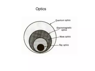
Spectrum • Optics concerns itself primarily with the visible and near IR region of the spectrum. • X-ray optics is a new and exciting field. • IR optics is a mature field due to military use. http://maths.newcastle.edu.au/phys1000/
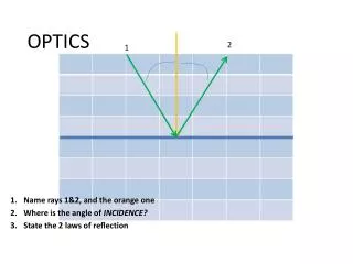
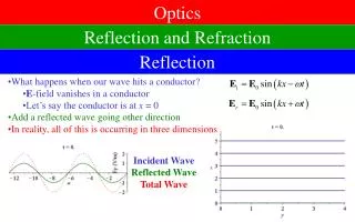
Reflections • Reflection from a surface may be diffuse or specular • Specular reflected light has the incident ray, the normal to the surface and the reflected ray in the same plane. The plane of incidence http://maths.newcastle.edu.au/phys1000/
Basic geometry http://maths.newcastle.edu.au/phys1000/
Terminology • Object distance d0 • Image distance di • Real image: the image is on the same side of the optical surface as the outgoing light. • Virtual image: the image is on the opposite side of the optical surface as the outgoing light. http://maths.newcastle.edu.au/phys1000/
Spherical aberration andparaxial approximation • A spherical surface is the easiest to manufacture • Parabolic surface is required to focus to a single point • Close to the axis (= paraxial) the spherical and parabolic surfaces do not differ much • Quite a useful approximation in geometric optics http://maths.newcastle.edu.au/phys1000/
Spherical mirrors • Within the paraxial approximation, rays parallel to the principal axis will focus at the focal point • Important points: Centre of curvature Focal point http://maths.newcastle.edu.au/phys1000/
Image Location Through Ray Diagrams I http://maths.newcastle.edu.au/phys1000/
Image location through ray diagrams II • Similar triangles OO’A and II’A • Similar triangles OO’F and ABF (within the paraxial approximation) leads to the mirror equation • Define the Lateral Magnification m http://maths.newcastle.edu.au/phys1000/
Image location through ray diagrams III • Virtual images • di negative (behind the reflecting surface) • do positive • f and r positive • m positive and >1 • Convex Optics • di negative (behind the reflecting surface) • do positive • f and r negative (behind the reflecting surface) • m positive and < 1 http://maths.newcastle.edu.au/phys1000/
Refraction • Regularly observed phenomena • Mirages • “Bent” teaspoon in water • Snell’s Law n1 sin1 = n2 sin2 • “n” index of refraction is defined by the electro-magnetic properties of a particular material. It varies with light of different wavelengths and is different for most materials http://maths.newcastle.edu.au/phys1000/
The spectrum of visible light and dispersion http://maths.newcastle.edu.au/phys1000/
Total internal reflection • For light passing from a medium with high index of refraction one of lower index of refraction, light is bent away from the normal • For light incident at < c some light will be refracted out of the medium • For light incident at > cnolight will be refracted out of the medium, it is totally internally reflected http://maths.newcastle.edu.au/phys1000/
Fibre optics http://maths.newcastle.edu.au/phys1000/
Lenses and optical instruments • Refraction at a surface will deflect light according to Snell’s Law. A lens refracts light a different amount at different distances from the center of the lens • An array of trapezoids will cause light from a point to refract in 2-D towards another point and serves to illustrate what a smoothly varying lens surface can do in 3-D http://maths.newcastle.edu.au/phys1000/
Lens: Converging or Diverging? • Light enters from the left, by convention • Converging lens are thicker in the middle than at the edges • Diverging lens are thinner in the centre than at the edges. • Many shapes are possible, each with their own focusing and aberration properties http://maths.newcastle.edu.au/phys1000/
Paraxial and thin lensapproximations • An aspheric surface is required to focus parallel rays of a single wavelength to the smallest point however a spherical surface is the easiest to manufacture. • Spherical aberration • Chromatic aberration • Close to the axis the spherical and aspherical surfaces do not differ much: Paraxial approximation. • “Thin Lens” approximation allows one to draw a ray through the vertex of the lens and simplify ray tracing. The diameter of the lens is smaller than the radii of curvature of the surfaces in this case. http://maths.newcastle.edu.au/phys1000/
Focal plane of a lens • The focal point is the image point for an object at infinity on the principal axis. • The distance of the focal point from the centre of the lens is the focal length • The Power of a lens in Diopters is the inverse of the focal length in metres. Power (Diopters) = 1/f(m) http://maths.newcastle.edu.au/phys1000/
Image location through ray diagrams I • These three rays allow the imaging properties to be determined graphically. • The image is real • On the same side of the lens as the outgoing light • The image is inverted • The focal length is positive by convention http://maths.newcastle.edu.au/phys1000/
Image location through ray diagrams II • The same approach of the three rays can determine the image of a diverging lens. • The image is virtual • It is on the other side of the lens from the outgoing light • The image distance is negative • It is on the other side of the lens from the outgoing light • The object distance is positive • The focal length is negative by convention as this is a diverging lens http://maths.newcastle.edu.au/phys1000/
The lens equation • Similar triangles FBA and FI’I • Similar triangles OAO’ and IAI’ (within the paraxial approximation) leads to the lens equation • Define the Lateral Magnification: m http://maths.newcastle.edu.au/phys1000/
Virtual image location through ray diagrams • Positive lens • do positive • di negative (opposite side of the lens from outgoing light) • m positive and >1 • f positive • Negative lens • do positive • di negative (opposite side of the lens from outgoing light) • f negative by convention • m positive and < 1 http://maths.newcastle.edu.au/phys1000/
Combination of lens • Use two or more lens in combination • Telescope • Microscope • Image from first lens becomes the object of the second http://maths.newcastle.edu.au/phys1000/
Example • Example: Two lens, both bi-convex converging lens withf1=20.0cm and f2=25.0cm, are placed 80.0cm apart. An object is placed in front of the first lens so that do =60.0cm. What is the positiondi and magnification mtotal of the final image? http://maths.newcastle.edu.au/phys1000/
Lensmaker’s equation I • How do you make a lens of a particular focal length? • Refraction at a spherical surface • Paraxial approximation: h is small. = + 2 and 1= + • R positive, doanddo positive http://maths.newcastle.edu.au/phys1000/
O I di do L I1 O R1 do di I1 I R2 di di L do Lensmaker’s equation II • Given a piece of glass in air with a refractive index of n and radii as shown we can apply the spherical refraction equation twice to arrive at the lensmaker’s equation. • Refraction atthe first spherical surface • Refraction atthe second spherical surface • Thin lens approximation: L<<diL0 • Already included the sign change for R1 and R2 so both radii are entered as positive values. http://maths.newcastle.edu.au/phys1000/
The human eye, a superb optical instrument. • Light enters through the cornea, where most refraction occurs, passes through the lens and forms an image on the retina. • The eye focuses on items of specific interest by squeezing the perimeter of the lens to form a crisp image on the fovea, the region of central and detailed colour vision. • This ability to accommodate between a relaxed state and nearby objects worsens with age as the lens becomes more crystalline. • Define the near and far points of vision. Far point is, ideally, infinity and near point is 25 cm for adults. http://maths.newcastle.edu.au/phys1000/
Common problems of the human eye: short-sightedness. • Nearsightedness has the image of an object at infinity forming before the retina. Vision of an object at infinity is corrected by a negative lens forming a virtual image at the person’s far point. http://maths.newcastle.edu.au/phys1000/
Common problems of the human eye: far-sightedness. • Farsightedness has the image of nearby object forming behind the retina. Vision of an object at 25cm, the standard near point, is corrected by a positive lens forming a virtual image at the person’s near point. http://maths.newcastle.edu.au/phys1000/
Other common problems of the human eye. • Astigmatism: An element of cylindrical correction. The image is distorted in a particular axis. Corrected by placing a rod-like lens at an appropriate angle. • Glaucoma: The pressure in the vitreous humor is too high. This causes shortsightedness and loss of vision through retinal problems. • Macula degeneration: Blood supply in the region of the macula is affected and vision is lost due to nerves being damaged. http://maths.newcastle.edu.au/phys1000/
Magnifying glass I • Close inspection differs from distant viewing by the size of the image on the retina. • The larger the angle subtended the greater the detail observed. • When direct vision is inadequate, we use a magnifying glass to enhance this further. http://maths.newcastle.edu.au/phys1000/
Magnifying glass II • Angular Magnification. http://maths.newcastle.edu.au/phys1000/
Telescopes • Refracting and reflecting telescopes have been made. The limit to refracting ones is the ability to make large, well corrected glass lens. • For a relaxed eye, fe= do and the distance between the lens is fo + fe. http://maths.newcastle.edu.au/phys1000/
Telescopes II • Newtonian and Cassegrainian reflecting telescopes are the styles most of the astronomical telescopes use for the reason that it is possible to make very large reflecting mirrors to high surface quality. • Hale 200 inch (5.08 m) at Mt. Palomar. • Keck 10 m effective diameter from 36 segments at Mauna Kea Hawaii. http://maths.newcastle.edu.au/phys1000/
Telescopes III • Terrestrial telescopes have upright images. • Galilean • Spyglass folded into binoculars http://maths.newcastle.edu.au/phys1000/
Microscopes • Object is placed in front of the objective lens and the object distance is just longer than the focal point. • Magnification is a product of the lateral magnification of the objective and angular magnification of the eyepiece. http://maths.newcastle.edu.au/phys1000/
Common aberrations in lens and mirrors • Spherical aberration • Due to reflecting or refracting surfaces being ground to spherical shapes when the ideal shapes are not spherical. Parabolic for mirrors. • Off-axis called coma. • Chromatic aberration • Affects lens due to dispersion in refractive index. Corrected by making compound lens from materials with slightly different RI and therefore dispersion. • Does not affect mirrors. http://maths.newcastle.edu.au/phys1000/
Huygen’s principle • Every point on a wavefront may be considered as a source of tiny wavelets that spread out in the forward direction at the speed of the wave itself. • The new wavefront is the summation of all the wavelets and is tangential to individual wavelets. http://maths.newcastle.edu.au/phys1000/
Diffraction • Huygens principle offers an explanation for the effects of diffraction around objects. • This is supportive of the wave theory of light. • In general diffraction is not observed with large aperture optics like windows but you certainly may observe diffraction with pinholes. http://maths.newcastle.edu.au/phys1000/
Wavefront refraction • Huygen’s principle is consistent with Snell’s Law of refraction. http://maths.newcastle.edu.au/phys1000/
Young’s double slit interference • Young’s observation when two slits were uniformly illuminated. • Consistent with interference between wavefronts emerging from each slit. http://maths.newcastle.edu.au/phys1000/
Young’s double slit interference II • Interference arises due to the path difference between light emerging from each slit varying as dsin. http://maths.newcastle.edu.au/phys1000/
Young’s double slit interference III • Overall intensity envelope is due to diffraction from each single slit. http://maths.newcastle.edu.au/phys1000/
L Line spacing for double-slit interference • A screen is 1.2m from two slits 0.100mm apart. 500nm wavelength light is incident upon the slit. What is the separation between bright fringes on the screen? • Given: d= 0.100mm = 1x10⁻⁴ m, =500x10-9 m, L= 1.20m http://maths.newcastle.edu.au/phys1000/
Wavelengths from double-slit interference • White light passes though two slits 0.5mm apart allows the measurement of wavelengths on a screen 2.5m away. The estimate of the violet and red wavelengths may be obtained. http://maths.newcastle.edu.au/phys1000/
Coherence • Interference is only possible if there is a fixed phase relationship between the radiation emerging from each of the two slits. • As the light source for Young’s fringes was a distant source, the sun, and as both slits “sampled” the wavefront at the same time, there was interference between the emerging wavefronts and these slits are then said to be coherent sources. • Most light sources are incoherent. An incandescent light bulb will emit light along the length of the filament. Light emitted at each end of the filament bears no phase relationship to the light emitted at the other. • Most lasers are sources of very coherent light. They may have a phase relationship which extends both across the beam and along the beam. This high degree of coherence is required to improve the contrast of interference fringes and in holography. http://maths.newcastle.edu.au/phys1000/
Intensity in the double-slit interference pattern • The electric field is given by the sum of the fields from each slit. These vary with angle in terms of a phase difference . • The intensity in the double slit interference pattern has periodic maxima corresponding to dsin =mlor, in terms of the phase difference : • The intensity in between these maxima may be determined as a function of angle . http://maths.newcastle.edu.au/phys1000/
Intensity in the double-slit interference pattern II • A phasor diagram illustrates the phase summation of the two equal fields. • Observe intensity rather than E field http://maths.newcastle.edu.au/phys1000/
Interference in thin films • An interference effect is seen in the reflection of light from water with a layer of oil on the surface. Rainbow coloured fringes are visible. • Light passing from material of lower to higher refractive index undergoes a 180° phase change upon reflection. (Higher to lower has no associated change.) • The additional optical path from A to B to C allows constructive interference when equal to a integer multiple of /noil. (It is assumed that nair > noil > nwater.) • The film thickness for normal incidence corresponding to a bright fringe is (/noil)/2. http://maths.newcastle.edu.au/phys1000/