Download
1 / 24
240 likes | 423 Vues
Ultrasonic Sensing and Collision Avoidance. Justin Holder Mike Schreppler. Introduction - Goals. Specific applications in automobiles Work as an aid in parking and low-speed maneuvers, help to avoid small “fender-benders”

E N D
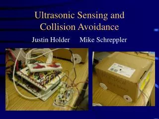
Ultrasonic Sensing and Collision Avoidance Justin Holder Mike Schreppler
Introduction - Goals • Specific applications in automobiles • Work as an aid in parking and low-speed maneuvers, help to avoid small “fender-benders” • Placement of sensors permits detection of objects that may not clearly be visible due to size or proximity to ground out of vision • Detection of objects suddenly in path
Introduction – System Feedback • Provide ‘real-time’ visual information in the form of a representation of the vehicle and distances to any immediate obstacle • Audio warnings for “eye-free” navigation; provides approximate range information in the form of audible tones • specifically designed for situations such as moving in reverse while your eyes are back and the visual display is forward
Introduction – Sensor Package • Using inexpensive, ultrasonic transmitter to emit an active signal, and will be heard by a complementary receiver • The time for reflection of the sound wave is measured, and a distance is determined
Original Design Proposal • Approximately 4 sensor pairs • (4) transmitters and (4) receivers • Display refresh speeds of less than 200 ms • Ideally less than 100 ms • Estimate speed of approaching obstacles and adjust warning appropriately
U/S Receiver Time Counter U/S Emitter Visual Output Sensor Select Master Controller Audio Output U/S Amplifier User Controls Original Design Block Diagram • U/S transmitter/receiver amplifier/filter • Master controller – HC11 • Visual output • Audio output • Time counter • User Inputs • Software flow chart
Approaching the Problem • Highly modular components, not interdependent • Visual, Sound, Transmit, and Receiver modules can separately work • All processes tie into the FPGA, which routes and calculates different data inputs • Components created and extensively debugged separately
Operation of Transmitter • FPGA tells to initiate signal • 6 MHz clock is made into a 40 kHz signal using two counters and other logic • 40 kHz signal is amplified from 5 V logic high to 15 V using a 1:3 multiplier • 15 V is sent to the transmitter
Operation of Receiver • Receiver listens to all frequencies • Amplifier boost signal from 10mV – 100mV to higher voltage level • LM567 Tone Detecting Operational Amplifier looks for 40 kHz in analog feedback; filter range ~ ± 2 kHz • 5 V logic high returned to FPGA
Operation of FPGA • Xilini Spartan II FPGA selected in research as superior product in terms or cost, number of gates (100k in our case), power consumption, available software, and ease of use • Conveniently, ECE249 had the same reasoning and purchased development board from Xess • Operating at 6 MHz – slowest clock in shop, yet still fast enough to process information efficiently • Code capable of operating at ~70 MHz • Speed / Bit trade off: faster the clock, more bits necessary to hold time-dependent information
Operation of FPGA • Center point of all processes in circuit • User controls: audio on/off, units cm/in • Sensor sweep: controls when and how long the transmitter will emit ultrasound; to transmitter amplifier • Sensor listen: listens to the amplifier/filter receiver for a returned signal detection • All timing and distance calculations • Send display information to display or external memory • All inputs/outputs buffered to protect board
Operation of FPGA • Highly modular, highly compartmentalized • Each idea has a separate procedure • e.g. divide, delay, ping, listen, timeconst, rangeinunits, savesignal, visual, audio, etc. • Can debug each part separately, used on-board 7 segment display to output a procedure “stage” number representing where the FPGA is currently in operation
Testing and Verification • Goal: display refresh times less than 100 ms • Product: each sensor requires a maximum of ~14 ms to run in worst case scenario • Intentional delay added to timing so that excess ultrasonic sound reflecting in environment can dissipate reducing random/false signal detections • Refresh rate selectable within VHDL code
Testing and Verification • Goal: reasonable accuracy, to several centimeters • Product: known to be accurate to less than 3 cm at 1 m distance • Designed for 2 m maximum distance detection • Measurements actually achieved to 2.5 m, though are cropped at 2m automatically
Challenges • FPGA clock not stable, varies ~ ±100kHz • VHDL has limited capabilities • No division, delay of up to 2 ms per sensor • No complex calculations in a single clock cycle • Shape of surface and medium affects distance that can realistically be detected
Successes • Integration of the modules successful • FPGA, Transmit, Receive, Display, Audio • Sensors detected objects beyond goal of 2m • Refresh rate of display very efficient • Accuracy of distance measured ~ 5% or less • Met product design deadline
Recommendations • Filter signal to transmitter – low pass • External registers to store values of multiple sensors • Use different FPGA prototype board • Improved Feedback • Selectable units (cm/in) • Better display with more sensors • Mutable audio • Time averaged measured value
Recommendations • Ideal display unit
Summary • Performance met all expectations • Created a platform that is easily upgradeable with additional sensors at minimal change of structure • With more time and additional hardware/software, the project could work much better