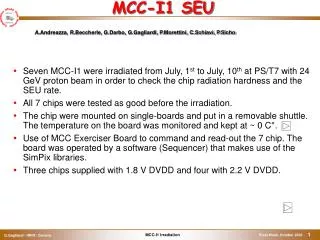
MCC-I1 SEU
MCC-I1 SEU. Seven MCC-I1 were irradiated from July, 1 st to July, 10 th at PS/T7 with 24 GeV proton beam in order to check the chip radiation hardness and the SEU rate. All 7 chips were tested as good before the irradiation.

MCC-I1 SEU
E N D
Presentation Transcript
MCC-I1 SEU • Seven MCC-I1 were irradiated from July, 1st to July, 10th at PS/T7 with 24 GeV proton beam in order to check the chip radiation hardness and the SEU rate. • All 7 chips were tested as good before the irradiation. • The chip were mounted on single-boards and put in a removable shuttle. The temperature on the board was monitored and kept at ~ 0 C°. • Use of MCC Exerciser Board to command and read-out the 7 chip. The board was operated by a software (Sequencer) that makes use of the SimPix libraries. • Three chips supplied with 1.8 V DVDD and four with 2.2 V DVDD. A.Andreazza, R.Beccherle, G.Darbo, G.Gagliardi, P.Morettini, C.Schiavi, P.Sicho
MCC-I1 Irradiation Beam Line
MCC-I1 Irradiation • The real time integrated dose measured by SEC chamber was 3.22 1015 proton/cm2. • The actual dose was monitored by Al foil placed behind each board. The activation measurements were consistent with each other. The mean measured value is 2.66 1015 proton/cm2. • Assuming the conversion factor of 54 /2 1015 Mrad/(proton/cm2) this leads to a conservative value for the integrated dose of ~ 71 Mrad.
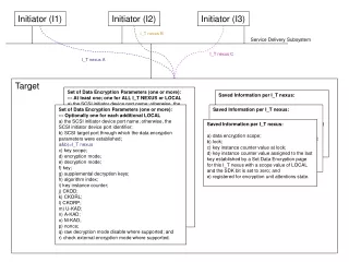
MCC-I2 Irradiation – SEU test • See Giovanni’s talk for test-beam operational experience and post-irradiation measurements. • The SEU test detected the modification of data stored into standard cell flip-flops (SC FF) and into the full custom memory cell of the Receiver FIFOs (FC MC) induced by the proton flux. • The Warning Front End register (WFE), the Warning MCC register (WMCC), the Front-End ENable register (FEEN) and the Pending Event FIFO (PEF) were the SCFF MCC-I1 memory element tested. • The SEU test was made by a writing phase before the spill and a reading phase after the spill. The chips’ clock was turned off during the spill in all but a few runs. • The writing phase of the SEU test loaded the SC FF and the FC MC with known values. Particular care was taken in balancing the number of memory bits set to 1 and to 0, in such a way to insure a uniform exposure for each internal structure during the irradiation. • During the SEU test writing phase the data stored in the SC FF and the FC MC were read back three times (except for the data stored into the PEF) to check that the write commands were decoded correctly. • The SEU test reading phase did also a three times check on the values read back. • All the seven chips under test were fully functional up to the end of the irradiation. This was checked by performing the SEU tests with the shuttle put in PARK position (far from the beam). No SEU’s were detected in those control runs. • A total of ~ 34500 spill has been put in tape; of those ~31000 are good for the analysis. This analysis refers to a sub sample of 15300 spill.
SEU effects – PEF • The SEU effect in the Pending Event FIFO (PEF) is detected as a change the data stored into the PEF locations by one or a few bits. spill 245 - mcc 5 - ok TRUE loc good bad 0 ffff ffff 1 eeee eeee 2 dddd fddd * 3 cccc cccc 4 bbbb bbbb 5 aaaa aaaa 6 9999 9d99 * 7 8888 8888 8 7777 7777 9 6666 6666 10 5555 5555 11 4444 4444 12 3333 3333 13 2222 22a2 * 14 1111 1111 15 0 800 * SEU (one star per bit flip) PEF location with SEU Expected values Read values
Global SEU effects – PEF • There are also SEUs that have a global impact (global SEU) on the data stored into the PEF. • The examination of the data read back from the PEF leads to the individuation of three categories of global SEUs. • The RESET: all the locations in the PEF are read back as zeroes. spill 251 - mcc 5 - ok FALSE loc good bad 0 ffff 0 **************** 1 eeee 0 ************ 2 dddd 0 ************ 3 cccc 0 ******** 4 bbbb 0 ************ 5 aaaa 0 ******** 6 9999 0 ******** 7 8888 0 **** 8 7777 0 ************ 9 6666 0 ******** 10 5555 0 ******** 11 4444 0 **** 12 3333 0 ******** 13 2222 0 **** 14 1111 0 **** 15 0 0
Global SEU effects – PEF • The REPEATED: the same value is read back starting from a PEF location. • This effect is understood as a SEU in the counter that controls the write PEF pointer. sp 638 - mcc 5 - ok FALSE loc good bad 0 0 0 1 1111 1111 2 2222 2222 3 3333 3333 4 4444 4444 5 5555 5555 6 6666 6666 7 7777 7777 8 8888 8888 9 9999 8888 **** 10 aaaa 8888 **** 11 bbbb 8888 ******** 12 cccc 8888 **** 13 dddd 8888 ******** 14 eeee 8888 ******** 15 ffff 8888 ************ spill 469 - mcc 1 - ok FALSE loc good bad 0 ffff ffff 1 eeee eeee 2 dddd dddd 3 cccc cccc 4 bbbb bbbb 5 aaaa aaaa 6 9999 9999 7 8888 8888 8 7777 7777 9 6666 6666 10 5555 5555 11 4444 4444 12 3333 3333 13 2222 3333 **** 14 1111 3333 **** 15 0 3333 ********
Global SEU effects – PEF • The SHIFT: the data are read consistently but in the wrong location. • This effect is still not fully understood but is related to SEU into the counter that controls the read PEF pointer and the related logic. • Those global SEUs (with many bit flips) have been taken away from the sample used to measure the SEU x-section for the SC FF. spill 289 - mcc 1 - ok FALSE loc good bad 0 ffff 7777 **** 1 eeee 6666 **** 2 dddd 5555 **** 3 cccc 4444 **** 4 bbbb 3333 **** 5 aaaa 2222 **** 6 9999 1111 **** 7 8888 0 **** 8 7777 ffff **** 9 6666 eeee **** 10 5555 dddd **** 11 4444 cccc **** 12 3333 bbbb **** 13 2222 aaaa **** 14 1111 999b ***** 15 0 8888 **** spill 443 - mcc 5 - ok FALSE loc good bad 0 ffff bbbb **** 1 eeee aaaa **** 2 dddd 9999 **** 3 cccc 8888 **** 4 bbbb 7777 ******** 5 aaaa 6666 ******** 6 9999 5555 ******** 7 8888 4444 ******** 8 7777 3333 **** 9 6666 2222 **** 10 5555 1111 **** 11 4444 0 **** 12 3333 ffff ******** 13 2222 eeee ******** 14 1111 dddd ******** 15 0 cccc ********
SEU effects – Receiver FIFO • The SEU effect in the Receiver FIFO FC MC is detected as a change the data stored into the Receiver FIFO locations by one or a few bits. . . . 107 50a14 50a14 108 4c993 4c993 109 48912 48911 ** 110 44891 44891 111 40810 40810 112 3c78f 3c78f 113 3870e 3870e 114 3468d 3468d 115 3060c 3860c * 116 2c58b 2c58b 117 2850a 2850a 118 24489 a4489 * 119 20408 20408 120 1c387 1c387 121 18306 18306 . . . • . . . • 50 dd932 dd932 • 51 dd9b3 dd9b3 • 52 dda34 dda34 • 53 ddab5 ddab5 • 54 ddb36 ddb36 • 55 ddbb7 ddbb7 • 56 ddc38 ddc38 • 57 ddcb9 ddcb9 • 58 ddd3a ddd3a • 59 dddbb ddcbb * • 60 dde3c dde3c • 61 ddebd ddebd • 62 ddf3e d5f3e * • ddfbf ddfbf • . . .
Global SEU effects – Receiver FIFO • We observe global SEU effects in the Receiver FIFOs. • The LOCATION 0: the content of the location 0 of one Receiver FIFO is corrupted (in most of the cases is set to 0). • spill 833 - mcc 7 • fifo 13 • loc good bad • isok FALSE • 0 1fffff 0 ********************* • 1 1fbf7e 1fbf7e • 2 1f7efd 1f7edd * • 3 1f3e7c 1f3e7c • 4 1efdfb 1efdfb • 5 1ebd7a 1ebd7a • 6 1e7cf9 1e7cf9 • 7 1e3c78 1e3c78 • 8 1dfbf7 1dfbf7 • 9 1dbb76 1dbb76 • 10 1d7af5 1d7af5 • 11 1d3a74 1d3a74 • 1cf9f3 1cf9f3 • . . . spill 845 - mcc 1 fifo 7 loc good bad isok FALSE 0 1fffff 4000 ******************** 1 1fbf7e 1faf7e * 2 1f7efd 1f7efd 3 1f3e7c 1f3e7c 4 1efdfb 1efdfb 5 1ebd7a 1e3d7a * 6 1e7cf9 1e7cf9 7 1e3c78 1e3c78 . . .
Global SEU effects – Receiver FIFO spill 771 - mcc 5 fifo 1 loc good bad isok FALSE 0 1fffff 1fffff 1 1fbf7e 1dbb7e ** 2 1f7efd 1f7efd 3 1f3e7c 1f3e7c 4 1efdfb 1efdfb 5 1ebd7a 1ebc7a * 6 1e7cf9 1e6cf9 * 7 1e3c78 1e3c78 8 1dfbf7 0 ****************** 9 1dbb76 dbb76 * 10 1d7af5 1d7af5 11 1d3a74 1d3a74 12 1cf9f3 1cf9f3 13 1cb972 1cb872 * 14 1c78f1 1c78f1 • The SINGLE LOCATION: the data stored in a Receiver FIFO location are corrupted, but not the data stored in the other locations of the same FIFO.
Global SEU effects – Receiver FIFO • The MULTIPLE LOCATION: many Receiver FIFO locations are corrupted. • Those global SEU affected events have been rejected from the sample used to measure the SEU x-section for the FC MC. • … • 28 18f1e3 100600 ************* • 29 18b162 180000 ******* • 30 1870e1 0 ********* • 31 183060 1f2400 ******* • 32 17efdf 1de00f ********* • 33 17af5e 1d000f *********** • 34 176edd b0600 ************ • 35 172e5c 100040 ********** • 36 16eddb 1 ************** • 37 16ad5a 6b *********** • 38 166cd9 3c00 ********** • 39 162c58 1e840f ********* • 40 15ebd7 1cc008 ************* • 41 15ab56 1de00f ********* • 156ad5 1de000 ********* • … spill 843 - mcc 5 fifo 7 loc good bad isok FALSE 0 1fffff 0 ********************* 1 1fbf7e 0 ****************** 2 1f7efd 1d7efd * 3 1f3e7c 1f3e74 * 4 1efdfb 1efdfb 5 1ebd7a 1fbd7a * 6 1e7cf9 1e7cf9 7 1e3c78 1e3c78 8 1dfbf7 1cfbf7 *
SEU x-section measure • A measure of the SEU x-section for the SC FF and FC MC has been done using the bit flip rate in the selected sample and the radiation dose recorded during the spills. • FC MC SEU x-section is twice as big than SC FF SEU x-section. • There is no definite increase of the SEU x-section with the integrated dose. • The chips supplied with 1.8 V DVDD have a SEU x-section for both FC MC and SC FF larger than the ones for 2.2 V DVDD chips. The 1.8V/2.2V SEU x-section ratio is ~ 2 for the SC FF and ~ 1.8 for the FC MC. • There is no definite difference between the 1 to 0 transition and 0 to 1 transition SEU x-section for SC FF. The SEU x-section 1->0/0->1 ratio for the FC MC shows an increasing with the integrated dose.
SC FF SEU x-section • This plot shows also the SEU x-section for two run with the clock on.
SEU FIFO spatial correlation • Looking at the Receiver FIFO locations with two bit flips there is evidence for the correlated production of FC MC bit flip in pairs. Only nearest neighbor double flip production is enhanced, i.e. there is no or very little correlation between FC MC bit flip production for which the spatial distance in the chip is greater than the size of the memory cell (in our case 5.60 mm). • The double bit flip excess is related to the energy released by a particle in the two FC MC. It is possible to measure the SEU FC MC nearest neighbor double bit flip in the Receiver FIFO locations. • The overall fraction of FC MC SEU nearest neighbor double flip is small, so that the effect on the FC MC SEU x-section is negligible (ranging from 0.3 to 0.5 % of the FC MC SEU x-section). • Work is still in progress to measure the double bit flip that occurs in the longer direction of the FC MC, and to disentangle the contribution from different bit flip patterns (11 -> 00, 10 ->01 etc)
SEU double flip spatial correlation Double bit flip excess Proton flux 5.5 1010/spill Integrated proton flux 1.01 1014 Random double bit flip in a FIFO location
SEU double flip spatial correlation Proton flux 1.3 1011/spill Integrated proton flux 1.35 1014
Global SEU effects x-section • An attempt to evaluate the SEU x-section for global effects has been done on the basis of SC FF and FC MC SEU x-section measured in the selected sample. • The statistics is poor since those effects are measured at the level of the Receiver FIFO and the PEF and not for individual memory cells. • PEF SHIFT, REPEATED and RESET SEU x-sections show a 1.8 V/2.2 V ratio similar to the SC FF SEU x-section one. • Receiver FIFO LOCATION 0 SEU x-section shows also 1.8 V/2.2 V ratio more compatible with SC FF SEU rather than FC MC SEU. • PEF SHIFT SEU x-section is ~ 9 times higher than the SC FF SEU x-section (not yet understood) • PEF REPEATED SEU x-section is 3 ~ 4 times higher than the SC FF SEU x-section (understood) • PEF RESET SEU x-section is of the order of the SC FF SEU x-section (understood) • Receiver FIFO LOCATION 0 is ~ 15 times higher than the SC FF SEU x-section (not yet understood) • Work still in progress…
SEU measured x-section and the Pixel Detector • Using the standard ATLAS irradiation figure for the B-Layer – 3x10¹⁴ proton/cm2 in one year (107 s) of data taking - it is possible to crude estimate the effect of the measured SEU x-section for the Pixel Detector. • Two effects are considered as benchmarks: the flipping of one of the memory cell of the hit FIFO that changes one hit word into an EoE word and the flipping of one of the ~2000 FF of the state machines in the MCC-I1. • In the pessimistic picture – i.e. data corruption and stop of standard behavior for the MCC-I1 every SC FF SEU flip, with one periodical reset every ~ 100 s and the chip operated at DVDD 2.2 V – the fraction of the data taking time when module data are corrupted is ~ 6%. • The inefficiency can be significantly reduced by ROD inspection of data and automatic recover. FC MC flip induced loss of event synchronization MCC-I1@2.2V ~3280 s (for the whole B-Layer ~11 s) MCC-I1@1.8V ~1860 s (for the whole B-Layer ~6 s) SC FF flip induced data corruption MCC-I1@2.2V ~1620 s (for the whole B-Layer ~6 s) MCC_I1@1.8V ~780 s (for the whole B-Layer ~3 s)
PEF+the other registers • The only other global effect when the chip is in the beam is the simultaneous reset of the PEF and the other three registers. • This simultaneous reset of the internal structures is limited one or a few chip for a spill. The occurring rate is uniform over the irradiation period and is in the range of 0.6 10-4 –1.8 10-4 reset/chip*spill WFE aaaa 0 ******** WMCC aaaa 0 ******** FEEN 5555 0 ******** sp 582- mcc 5- ok 0- loc good bad 0 0 0 1 1111 0 **** 2 2222 0 **** 3 3333 0 ******** 4 4444 0 **** 5 5555 0 ******** 6 6666 0 ******** 7 7777 0 ************ 8 8888 0 **** 9 9999 0 ******** 10 aaaa 0 ******** 11 bbbb 0 ************ 12 cccc 0 ******** 13 dddd 0 ************ 14 eeee 0 ************ 15 ffff 0 **************** probable chip reset at spill 582 mcc 5 16-bit Registers PEF
Beam Profile 0 7 8 F