Download
1 / 17
170 likes | 338 Vues
Fall 2004 AGU Meeting, San Francisco SH31B-07 GROUND-BASED COSMIC RAY DETECTORS FOR SOLAR-TERRESTRIAL RESEARCH AND SPACE WEATHER FORECASTING. John W. Bieber 1 , John Clem 1 , Paul Evenson 1 , Kazuoki Munakata 2 , and Roger Pyle 1

E N D
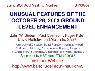
Fall 2004 AGU Meeting, San Francisco SH31B-07GROUND-BASED COSMIC RAY DETECTORS FOR SOLAR-TERRESTRIAL RESEARCHAND SPACE WEATHER FORECASTING John W. Bieber1, John Clem1, Paul Evenson1, Kazuoki Munakata2, and Roger Pyle1 1. University of Delaware, Bartol Research Institute, Newark 2. Shinshu University, Physics Department, Matsumoto, Japan Supported by NSF grant ATM-0000315 Visit our Website: http://neutronm.bartol.udel.edu/
OBSERVATION OF COSMIC RAYSWITH GROUND-BASED DETECTORS • Ground-based detectors measure byproducts of the interaction of primary cosmic rays (predominantly protons and helium nuclei) with Earth’s atmosphere • Two common types: • Neutron Monitor Typical energy of primary: ~1 GeV for solar cosmic rays, ~10 GeV for Galactic cosmic rays • Muon Detector / Hodoscope Typical energy of primary: ~50 GeV for Galactic cosmic rays (surface muon detector)
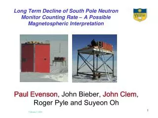
NEUTRON MONITORS • Older type “BP28” – proportional counter filled with BF3: n + 10B → α + 7Li • Modern type – counter filled with 3He: n + 3He → p + 3H • Both types some-times called “NM64” Neutron Monitor in Nain, Labrador Construction completed November 2000
Spaceship Earth Spaceship Earth is a network of neutron monitors strategically deployed to provide precise, real-time, 3-dimensional measurements of the cosmic ray angular distribution: • 11 Neutron Monitors on 4 continents • Multi-national participation: U.S.A., Russia, Australia, Canada
SPACESHIP EARTH VIEWING DIRECTIONS • Optimized for solar cosmic rays • 9 stations view equatorial plane at 40-degree intervals • Thule and McMurdo provide crucial 3-dimensional perspective Circles denote station geographical locations. Average viewing directions (squares) and range (lines) are separated from station geographical locations because particles are deflected by Earth's magnetic field. STATION CODES IN: Inuvik, Canada FS: Fort Smith, Canada PE: Peawanuck, Canada NA: Nain, Canada MA: Mawson, Antarctica AP: Apatity, Russia NO: Norilsk, Russia TB: Tixie Bay, Russia CS: Cape Schmidt, Russia TH: Thule, Greenland MC: McMurdo, Antarctica
RELATIVISTIC SOLAR PARTICLES OBSERVED BY NEUTRON MONITORS: OCTOBER 28, 2003 (a) Solar neutron increase at Tsumeb, Namibia (b) Solar protons at several high-latitude monitors (c) Omnidirectional intensity with model fit (d) Derived injection profile at Sun For details see: • Clem et al., SH13A-1136, this conference • Bieber et al., Geophys. Res. Lett. (special issue on Nov-Oct 2003 solar activity), in press.
NAGOYA-TYPE MUON DETECTOR • Coincidences between top and bottom layers provide information on incident direction of cosmic ray primary • A single detector measures intensity in several directional channels (e.g., 17 at Nagoya)
SKY COVERAGE OFMUON DETECTOR NETWORK • Blue symbols show viewing directions (median rigidity) covered by existing network • Red symbols show new viewing directions from planned enlargement of the network • Curves show the range of viewing directions for the central 80% of detector energy response
A SAMPLE APPLICATION: REMOTE SENSING SOLAR WIND DISTURBANCES • B×Gradientanisotropy : IMF unit vector : density gradient vector ecliptic plane : Larmor radius ~0.2 AU for muons ーG⊥ pointing toward CME center
DETERMINATION OF ICME GEOMETRYFROM COSMIC RAYS • Left: Measured and modeled cosmic ray gradients during an ICME on October 29, 2003 • Right: ICME geometry inferred from cylinder model • Figures adapted from Kuwabara et al., Geophys. Res. Lett., 31, L19803, 2004. • See also Kuwabara et al., SH53B-0331, this conference.
MUON HODOSCOPES:A DENSE DIRECTIONAL NETWORK • Newer technologies permit fine scale mapping of cosmic ray anisotropies • Map shows view directions for Mt. Norikura, Japan (red)and Project GRAND, Notre Dame Univ (blue)
Intensity deficit confined in a cone Loss-cone precursors Nagashima et al. [1992], Ruffolo [1999]
A COSMIC RAY LOSS CONEOBSERVED ON OCTOBER 28, 2003 • Mt Norikura field of view over a 6-hr period prior to storm sudden commencement. TOP: Observations. BOTTOM: Model • Blue indicates lower intensity; Red indicates higher intensity • Figures from Munakata et al., Geophys. Res. Lett. (special issue on Nov-Oct 2003 solar activity), in press. • See also Munakata et al., SH53B-0322, this conference.
SPACE WEATHER APPLICATIONS • Numerous stations provide realtime displays of raw count rate data • Univ Delaware / Bartol site (left) provides higher level data, including realtime displays of cosmic ray • Density • Flow direction • Pitch angle distribution • For details see Pyle et al., SH41A-1074, this conference http://neutronm.bartol.udel.edu/spaceweather/
SUMMARY • Ground-based cosmic ray detectors remain the state-of-the-art instrumentation for studying high-energy (>1 GeV) cosmic rays • The data are of use both for basic space physics research and for space weather forecasting and specification • Strategically sited new instruments are needed to fill gaps in sky coverage, but … • Much can also be gained by linking existing instruments in coordinated realtime networks