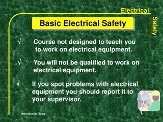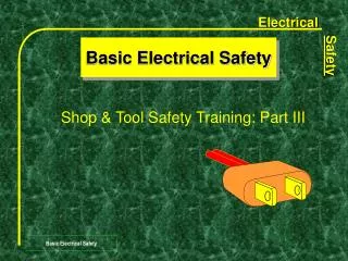
Protecting Load & Personnel: SafetyBASICs™ Fuseology Guide
Enhance safety awareness with insights on overcurrent protection devices, interruption ratings, and fault current limitations. Learn about current-limiting safety measures to prevent equipment damage and ensure personnel safety.


Protecting Load & Personnel: SafetyBASICs™ Fuseology Guide
E N D
Presentation Transcript
SafetyBASICsTM Fuseology For Safety & Protection Bussmann’s Awareness of Safety Issues Campaign
Available Short Circuit Current Over Current Protection Device Load to be Protected Load Current Safety BASICsTM Fuseology Interrupting Rating(NEC 110-9) Safety & Protection Reservoir Analogy
FAILURE of Over Current Protection Device Available Short Circuit Current Short Circuit Current Load (Equipment) Damaged, Possible Personnel Injury Safety BASICsTM Fuseology Interrupting Rating(NEC 110-9) Safety & Protection Reservoir Analogy
Available Short Circuit Current Proper Operation of Over Current Protection Device If the device opens in less than 1/4 cycle it’s considered Current Limiting Short Circuit Current Safety BASICsTM Fuseology Current limitation(NEC 240-11) Safety & Protection Reservoir Analogy
Available Fault Current Reduced Fault Current Non-Current Limiting Current Limiting Safety BASICsTM Fuseology Current limitation(NEC 240-11) Safety & Protection A Current-Limiting Overcurrent Protection Device
Available Fault Current Reduced Fault Current Non-Current Limiting Current Limiting Safety BASICsTM Fuseology Current limitation(energy reduction) Safety & Protection • Consider that: • Magnetic Forces -- varies with the square of the Peak Current • Thermal Energy -- varies with the square of the RMS Current
Reduced Fault Current Current Limiting Safety BASICsTM Fuseology Current limitation(ex.: LPJ_SP) Safety & Protection
Example of Type”1” Motor Starter protection Safety BASICsTM Fuseology Component Protection • Type “1” protection allows for significant damage to motor starters requiring replacement. (similar to UL 508) • Type “2” coordinated “No Damage” protection provides for minimal damage and ability to reuse the starter. Safety & Protection
Barrier, Wall or Isle with an Combination obstruction Controller While this is not required (because the Switch is switch ahead of the controller can be capable of locked in the off position) it is being locked desirable for the situation where in the open someone accidentally gets “caught position up” in the motor/machine. M Supplementary Motor Disconnect Safety BASICsTM Fuseology “Supplementary” Disconnecting Means • The disconnect at the controller may be difficult to quickly reach in an emergency Safety & Protection
Safety BASICsTM Fuseology Definition -- “Selective Coordination” The act of isolating a faulted circuit from the remainder of the electrical system, thereby eliminating unnecessary power outages. The faulted circuit is isolated by the selective operation of only the overcurrent protective device closest to the overcurrent condition. Safety & Protection
OPENS OPENS NOT AFFECTED NOT AFFECTED FAULT FAULT UNNECESSARY POWER LOSS Safety BASICsTM Fuseology Selective Coordination Without Selective CoordinationWith Selective Coordination Safety & Protection
Thermal Magnetic • MC Circuit Breaker • Time-Current Curve • Overload Region • Instantaneous Trip • Instantaneous Region • Unlatching Time • Interrupting Time • Interrupting Rating Safety BASICsTM Fuseology Selective Coordination Safety & Protection
Safety BASICsTM Fuseology Selective Coordination Blackout Condition • 90A & 400A Molded Case Circuit Breakers • Inherent long delay between unlatching and interrupting due to mechanical means of breaking current • Upstream breaker can unlatch before the downstream breaker can clear the fault • Lack of Selective Coordination in the Short-Circuit Region Safety & Protection
Insulated Case CB • 2000A Insulated Case Circuit Breaker • STD is an Option - allowing the breaker to delay opening • Instantaneous Override built-in: may be as low as 12X the breaker rating • Will often result in lack of coordination Safety BASICsTM Fuseology Selective Coordination Safety & Protection
Safety BASICsTM Fuseology Selective Coordination Insulated Case CB • 2000A Insulated Case Circuit Breaker with Short Time Delay, Instantaneous Override and 100A Molded Case Thermal Magnetic Circuit breaker - NO Coordination in Short-Circuit Region (above 21,000A) Safety & Protection
LV Air Power CB • Low Voltage Power Circuit Breakers • Short Time Delay - Allows the fault current to flow for up to 30 cycles. • Can be used to selectively coordinate with downstream devices. • Subjects equipment to high mechanical and thermal stresses, often violating 110-10. • High Cost, Larger Safety BASICsTM Fuseology Selective Coordination Safety & Protection
Safety BASICsTM Fuseology Selective Coordination • Fuses Coordinate in Overload AND Short-Circuit Regions • Overload - Time Current Curves • Short Circuit - Selectivity Ratio Guide (based on I2t) Safety & Protection
Safety BASICsTM Fuseology Selective Coordination • Short Circuit Region • Coordination in the Overload region Safety & Protection
Safety BASICsTM Fuseology Selective Coordination • Short Circuit Region • Selectivity Ratio • Guide (based on I2T) Safety & Protection
Safety BASICsTM Fuseology Selective Coordination Safety & Protection Ratio Guide assures selective fuse coordination
Safety BASICsTM Fuseology Arch-Flash test set-up Test conducted at the Paul P. Gubany Center for High Power Technology Safety & Protection
Protected with a 601 Amp. Current Limiting Class L fuse. (Slight splatter of molten metal) Protected with a 1600 Amp. Non-Current Limiting Circuit Breaker set at 640 Amps. with short time delay of 12 cycles. Safety BASICsTM Fuseology Benefits of “Current-Limitation” *Tests with 22,600 Amperes of fault current Safety & Protection