Download
1 / 36
360 likes | 513 Vues
Beam Instrumentation Tests for the Linear Collider. SLAC EPAC Meeting Nov. 14, 2003. M. Woods, SLAC. Luminosity, Energy and Polarization measurements at the Linear Collider (LC-LEP measurements) SLAC A-Line and End Station A Facility Beam Characteristics and Comparison with NLC Beam

E N D
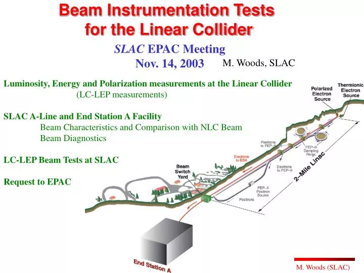
Beam Instrumentation Tests for the Linear Collider SLAC EPAC Meeting Nov. 14, 2003 M. Woods, SLAC Luminosity, Energy and Polarization measurements at the Linear Collider (LC-LEP measurements) SLAC A-Line and End Station A Facility Beam Characteristics and Comparison with NLC Beam Beam Diagnostics LC-LEP Beam Tests at SLAC Request to EPAC M. Woods (SLAC)
Beam Instrumentation Tests for the Linear Collider using the SLAC A-Line and End Station A Y. Kolomensky University of California, Berkeley J. Hauptman, O. Atramentov Iowa State University E. Gulmez,† E. Norbeck, Y. Onel, A. Penzo* University of Iowa D. J. Miller University College London R. Arnold, S. Hertzbach, S. Rock University of Massachussets M. Hildreth University of Notre Dame E. Torrence University of Oregon J. Clendenin, F.-J. Decker, R. Erickson, J. Frisch, L. Keller, T. Markiewicz, T. Maruyama, K. Moffeit, M. Ross, J. Turner, M. Woods SLAC W. Oliver Tufts University G. Bonvicini, D. Cinabro Wayne State University SLAC-LOI-2003.2 27 physicists 10 institutions †also Bogazici University, Istanbul, Turkey *also INFN Trieste, Italy http://www.slac.stanford.edu/grp/rd/epac/LOI/LOI-2003.2.pdf
Luminosity, Energy and Polarization measurements at the Linear Collider (LC-LEP measurements) M. Woods (SLAC)
ALCPG Working Group IP Beam Instrumentation WG Scope Beam Instrumentation required for LC Physics • PrincipleTopics (L,E,P) • Luminosity, luminosity spectrum (dL/dE) • Energy scale and width • Polarization • Also • Instrumentation for optimizing Luminosity • - IP BPMs for fast feedback and feedforward • - detectors for pairs, beamstrahlung, radiative Bhabhas M. Woods (SLAC)
LC-LEP Measurement Goals • Luminosity, Luminosity Spectrum • Total cross sections: absolute dL/L to ~0.1% • Z-pole calibration scan for Giga-Z: relative dL/Lto ~0.02% • threshold scans (ex. top mass): relative dL/Lto 1% • +L(E) spectrum: core width to <0.1% and • tail population to <1% • Energy • Top mass: 200 ppm (35 MeV) • Higgs mass: 200 ppm (25 MeV for 120 GeV Higgs) • W mass: 50 ppm (4 MeV) ?? • ‘Giga’-Z ALR: 200 ppm (20 MeV) (comparable to ~0.25% polarimetry) • 50 ppm (5 MeV) (for sub-0.1% polarimetry with e+ pol) ?? • Polarization • Standard Model asymmetries: < 0.5% • ‘Giga’-Z ALR: < 0.25%
Beamstrahlung at the Linear Collider Energy spectrum of electrons in extraction line after IP at NLC-500 ~7% of the beam energy gets radiated into photons due to beamstrahlung (at SLC this was 0.1%) disrupted beam (w/ beamstrahlung radiation effect included) from pair production radiative Bhabhas
The beam diagnostics measure <E>, <P>. For physics we need to know <E>lum-wt, <P>lum-wt . 100-200 ppm physics goal for determining <E>lum-wt << 3000ppm energy spread <<< 70,000 ppm energy loss due to beamstrahlung! Strategy is to use a combination of beam diagnostics and physics-based detector measurements. Need to understand L(E) spectrum and how it is affected from beamstrahlung and energy spread, as well as from initial state radiation. How well the luminosity-weighted quantities can be determined depends on the beam parameters at the IP, as well as on the intrinsic capabilities of the polarimeter and the energy spectrometers.
p1 LC Detector Measurements of L(E), <E>lum-wt, <P>lum-wt q1 z-axis q2 p2 These techniques don’t replace the need for real-time beam-based measurements. Want complementary and/or combined analyses with beam-based measurements. Luminosity Spectrum, L(E) Bhabha Acolinearity: <E>lum-wt Radiative return to Z events W-pair events <P>lum-wt Asymmetry in forward W-pairs
Example of Lum-wted Energy Bias related to Beam Energy Spread at NLC-500 Lum-wted ECM Incident beam Tail Incident beam Head For this study, turn off ISR and beamstrahlung and only consider beam energy spread. Bhabha acolinearity analysis alone won’t help resolve this bias.
Instrumentation for Luminosity, Luminosity Spectra and Luminosity Tuning Luminosity Bhabha LuMon detector from 40-120 mrad Luminosity Spectrum Bhabha acolinearity measurements using forward tracking and calorimetry from 120-400 mrad + additional input from beam energy, energy spread and energy spectrum measurements Luminosity Tuning Pair LuMon detector from 5-40 mrad Beamstrahlung detector from 1-2 mrad (further downstream) IP BPMs
Forward Tracking, Calorimetry and Masking (for NLC Silicon Detector) 0.5 113mrad 0.4 0.3 0.2 Bhabha LuMon Tungsten y (meters) incoming e+ 0.1 Pair LuMon 46mrad QD0 0 LowZ Mask Exit radius 2cm @ 3.5m outgoing e- BeamPipe -0.1 Tungsten -0.2 Support Tube -0.3 ECAL -0.4 HCAL YOKE -0.5 0 0.5 1 1.5 2 2.5 3 3.5 4 z (meters from IP) IP BPMs for fast feedback and feed forward @ ~z = 3.5 meters
Using Pairs and Beamstrahlung for Luminosity Tuning • 7 degrees-of-freedom for colliding bunches: • individual spotsizes (4) • relative offset (2) • relative tilt of bunches (1) 2 promising detector techniques for determining beam offsets and individual beamsizes: • Angular distributions of low energy e+e- pairs from 2-photon processes • T. Tauchi and K. Yokoya, Phys. Rev. E51 (1995) 6119-6126. • Measuring polarization of the beamstrahlung emitted at angles of (1-2) mrad. • G. Bonvicini, N. Powell (2003) hep-ex/0304004; submitted to Phys.Rev.E
Using IP BPMs for Luminosity Tuning Fast IP Beam diagnostics must work as planned and be robust against backgrounds NLC e+e- TESLA e+e- NLC e+e- TESLA e+e- Deflection angle vs vertical offset Luminosity vs vertical offset Slow (inter-train) and fast(ns-timescale intra-train) feedbacks are planned Two of the highest risk factors for achieving LC design luminosity are: i) reliance on IP feedbacks and ii) effects of backgrounds (beam-beam and other) on detectors and beam instrumentation
Instrumentation for Energy, Energy Spread and disrupted Energy Spectrum Energy BPM spectrometer (upstream of IP) Synchrotron Stripe spectrometer (in extraction line) Energy Spread Synchrotron Stripe spectrometer (in extraction line) Wire scanner at high dispersion point in extraction line chicane Disrupted Energy Spectrum Synchrotron Stripe spectrometer (in extraction line) Wire scanner at high dispersion point in extraction line chicane Synchrotron Stripe Spectrometer at SLC Proposed BPM spectrometer at NLC
Chicane bend magnets Instrumentation for Polarimetry Compton Polarimeter in Extraction Line
LCRD and UCLC FY04 R&D Proposals to DOE and NSF Luminosity Fast Gas Cherenkov Calorimeter (Iowa St.) Parallel Plate Avalanche, Secondary Emission Detectors (Iowa) Large Angle Beamstrahlung Monitor (Wayne St.) 3d Si Detector for Pair Monitor (Hawaii) Energy Synchrotron Stripe Spectrometer (Oregon, UMass) rf BPM Spectrometer (Notre Dame, UC Berkeley) Polarization Quartz Fiber Calorimeter; W-pair asymmetry (Iowa) Background study (Tufts) Quartz Fiber Detector; transverse polarization (Tennessee) M. Woods (SLAC)
SLAC A-Line and End Station A Facility for LC-LEP measurements
SLAC A-Line and End Station A Facility • Beam Characteristics and Comparison with NLC Beam • Beam Diagnostics
NLC Bunching Study LI30 201X BPM electrode signal PPRC is starting a new R&D project to achieve 714MHz modulation (1.4ns bunch spacing) of the Long Pulse laser used for the Source - will use an electro-optic modulator driven with 714MHz rf - will experiment both with intra-cavity modulation and an external modulator Use 178.5MHz SHB cavity • Bunch Train with • 5.6ns spacing • ~1010 bunch charge But, beam in LINAC is unstable. - some evidence for beam breakup - needs further study
Agreement (MeV) BPM24 X (MeV) energy ~1 MeV toroid~30 ppm BPM12 X (MeV) Beam Diagnostics for SLAC E-158 BPM~2 microns
A-Line Synchrotron Light Monitor (SLM) visible SR electron beam visible SR imaging telescope gated ccd camera Energy and Energy spread (in MeV) in 60-ns time slices along the 300ns train for 45 GeV beam
End Station Aconfigured for E-158 Target chamber Quadrupoles Target Station Detector Cart Concrete Shielding Beam Monitors Luminosity Monitor Dipoles Drift pipe 60 m
<5mrad production angle • 2. Mimick ‘beamstrahlung and disruption’ • for IP bpms using a thick target in ESA; • compare LC bpm measurement 4 meters downstream • of target with precision upstream bpms NLC-500 ESA-25GeV (w/ 10% X0 Carbon target) BPM Tests (Energy Spectrometer BPMs and IP BPMs) • Characterize performance of LC BPMs • Temporal response and resolution; compare • with existing high resolution diagnostics • (SLM at high dispersion point and wire array • at target) A-Line 45 GeV Beams can have temporal ‘banana’ shape in position, angle, energy
Accelerator Facilities for LC BPM Tests *new PPRC project is attempting to produce 714MHz modulation of long pulse beam †ATF will attempt 3-train operation with 60-ns gaps between trains for 300-ns train length
Similar divergences and spotsizes at IP BPM location Comparison of Beam Spotsizes and Divergences at NLC-500 and ESA (w/ 10% X0 target)
Photon Distributions downstream of IP(Target) NLC-500 ESA-25GeV
>5mrad production angle >5mrad production angle Beam Tests for Pair detectors Positron Spectra Electron Spectra NLC-500 (per colliding bunch) ESA-25GeV (per 20K incident electrons on 10% X0 target) NLC-500 (per colliding bunch) ESA-25GeV (per 20K incident electrons on 10% X0 target) • Test performance of high rate pair detector • - use thinner target to match rates and hit density • - test temporal response over 300ns train
Beam Tests for Synchrotron Detectors (for energy spectrometer, possibly for beamstrahlung detector) • Improve instrumentation for existing SLM in A-Line • Commission new synchrotron stripe detectors in ESA • Mirrors and ccds for visible SR • Quartz fibers w/ multi-anode PMT readout for ~MeV SR • test capability for resolving beam energy spread and hard edge at NLC-500 (w/ energy spread) ESA-25GeV (w/o energy spread, w/ 10% X0 target)
Energy Spectrometer Beam Tests • Implement both BPM and synchrotron stripe energy spectrometers. • Compare their performance directly, including capabilities for resolving energy • variations along 300-ns train • Compare energy jitter and energy temporal profile with existing instrumentation • using BPMs and the SLM at high dispersion points in the A-Line • 24.5-degree A-line bend angle gives 180-degree spin precession every “3.237” GeV • Use energy scans across 2 or 3 zero-crossings of the polarization, where the beam • longitudinal polarization is measured with a Moller or Compton polarimeter. • Compare new energy spectrometer results with polarization results. (Can also • check comparison with A-line flip coil and power supply currents.) • 10-3 accuracy from spin precession should be possible; whether 100-200 ppm • is feasible needs study.
Polarimetry Beam Tests • Install a Compton polarimeter • Reuse hardware from SLD Compton polarimeter • Commission new detectors and make independent asymmetry measurements with • complementary detectors to evaluate systematics • - compare electron and photon measurements • - compare counting mode versus integrating mode • Measure temporal dependence of polarization along the 300-ns train • With chicane for polarimeter downstream of target, can commission measurement • in presence of bremsstrahlung mimicking the beamstrahlung
General Comments • Extraction Line Instrumentation (after IP) • More flexibility to implement optimized beam optics for the instrumentation. • No constraint to avoid emittance degradation. (Ex: can have x10 larger bend • angles for the energy spectrometer) • Can measure beam-beam effects (luminosity, disruption, beamstrahlung, depolarization) • Can still measure undisrupted beam parameters, by requiring ~2% of pulses to be • single beam (no collisions) • Energy spectrometer and polarimeter can be closer to the IP. • LC luminosity and LC physics capabilities • Any beam or detector instrumentation that cannot be commissioned until the LC is built • have very high risk factors. Do beam tests early!
Impact on LC Design • There’s a close interplay between machine parameters and beam optics design with the • measurements discussed here. What we learn from these LC-LEP beam tests and • simulation studies can impact the machine design. • Co-ordination with European and Asian Activities • The UK Linear Collider group is focusing on the beam delivery system, including • some of the beam instrumentation discussed in this LOI. They have recently • been awarded ~$8M Euros (over 3 years) from PPARC for their LC activities on the • Accelerator. One of the UK groups (UC London; David Miller) has already • joined this LOI. • The LCRD proposal for a pair detector involves a collaboration with Tohoku U. in • Japan and we would hope to test this detector in the ESA beam tests. • The beam-beam simulation codes in use are GUINEA-PIG (European code) and • CAIN (Japan and US code). Further checks of these codes with both simulations • and experiment are very desirable, in particular for understanding the tails of the • disrupted beam distributions and the PT spectrum of the pairs. Comparisons with • beam distributions from a thin fixed target, both with EGS simulation and experimental • measurements may be useful.
Requests to EPAC • Recognize importance of SLAC’s Polarized Electron Source, A-Line and • End Station A facilities for LC-LEP beam tests. (Currently there are no • approved physics experiments at SLAC requiring a polarized beam or a • high power long-pulse beam.) 2. Recommend that SLAC take into consideration LC-LEP beam tests, when modifying the A-Line and ESA beamlines, or the Polarized Source. (Also need compatibility with Linac modifications for LCLS.) 3. Encourage the development of (full technical) proposals for LC-LEP beam tests. • Recommend that SLAC allow for a 1-week beam test in FY05 and • 1-2 week beam tests in FY06 and FY07 in the long-range accelerator planning.
Conclusions We have presented a description of LC-LEP measurements that are required by the LC physics program, as well as critical instrumentation that is needed for realizing the LC luminosity goals. The long pulse polarized beam to End Station A reflects many of the beam characteristics for the NLC beam at a 500-GeV collider. We have described how the existing beam and beam diagnostics can be utilized for LC-LEP beam tests. We have presented an overview of LC-LEP beam tests that can be carried out at SLAC’s ESA to demonstrate the stringent requirements for the detectors and techniques to be employed at the Linear Collider. There is much work to do to carefully design meaningful and cost-effective beam tests. We can be ready for first beam tests in FY05.