Understanding Thyristor Operation and Its Application in Three-Phase Controlled Rectifiers
60 likes | 198 Vues
This article explores the operation of thyristors, including their gating conditions and conduction behavior. It explains how a thyristor remains in a conductive state (latching) even after gate voltage removal when VAK is positive. The concept of firing angle (α) in both single-phase and three-phase rectifiers is discussed, along with the impact of firing delays and overlap losses on voltage-timing areas. Additionally, it covers current waveforms, displacement, and distortion factors associated with three-phase fully controlled bridge rectifiers, key to efficient DC motor operation.

Understanding Thyristor Operation and Its Application in Three-Phase Controlled Rectifiers
E N D
Presentation Transcript
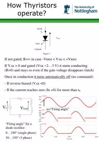
How Thyristors operate? • If not gated, R= in case -VRRM < VAK < +VRRM • If VAK > 0 and gated (VGK =2…5 V) it starts conducting (R=0) and stays so even if the gate voltage disappears (latch) • Once in conduction it turns automatically off (no command): • If reverse biased (VAK <0) • If the current reaches zero (IK =0) for more than tq Vs Vload =“Firing angle” “Firing angle” for a diode rectifier: 0…180 (single phase) 30…150 (3-phase)
3-phase Fully Ctrl Bridge Rectifier (1) h Line A Id=const A x T1 T5 T3 a’ Neutral b’ Vxy c’ 0 h T4 T6 T2 C y B h ia Armature winding of DC motors for 4-quadrant operation (elevators) = 30 T1 T3 T5 Vx T4 T6 T2 Vy Vxy ia
3-phase Fully Ctrl Bridge Rectifier (2) Volt-time area loss due to overlap Volt-time area loss due to delayed firing Volt-time area loss due to the firing delay Adjustable Loss of mean voltage from Vx Loss from Vxy Ideal diode rectifier
3-phase Fully Ctrl Bridge Rectifier (3) h A Id=const x T1 T3 ia VBA a’ b’ ib 0 h B Voltage drop due to overlap is the same as in the 3-phase diode rectifier Calculation of Easiest way to find it is by considering the following loop: VBA Area = 2 Id *h • During this time, Vba causes the change of : • ia from Id to 0 • ib from 0 to Id
3-phase Fully Ctrl Bridge Rectifier (4) Line Current Waveforms +Id +30 120 -Id 0 T/2 T Exactly the same waveform as for the diode rectifier but displaced by > Id (peak) RMS input current: Displacement factor DPF = cos () Distortion factor DF = Power factor PF is very poor at low output voltage near 90