Download
1 / 30
300 likes | 323 Vues
Understand the working principles, technology types, electrical characteristics, and power conversion implications of fuel cells for efficient energy conversion applications.

E N D
Fuel Cells: Electrical Energy Conversion Issues SeminarNovember 2002 P. T. Krein Grainger Center for Electric Machinery and Electromechanics Dept. of Electrical and Computer Engineering University of Illinois at Urbana-Champaign
Outline • How do fuel cells work? • Some technology types. • Electrical characteristics. • Implications for power conversion. • Key components for low-cost fuel cell conversion applications. • Conclusion.
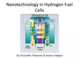
How Do Fuel Cells Work? • Two reactive components are separated by an “ionic conductor” (electrolyte). • Most widely used example: hydrogen and oxygen. • Protons flow through the electrolyte. • Electrons flow through an external circuit. • The electrochemical potential is defined by the specific reaction.
How Do Fuel Cells Work? • The system is like a “proton diode.” • The action is like a battery, except that the fuel and oxidizer are allowed to “flow through,” leading to continuous operation. • Energy conversion efficiency is high.
Technology Types • Fuel cell technologies are determined by the selected fuel and by the electrolyte. • Fuel: • Hydrogen • Zinc metal • Other hydrocarbons • Electrolyte: • Phosphoric acid • Proton exchange membrane (PEM) • Solid-oxide (SOFC) • Molten carbonate
Technology Types • Most types are intended for hydrogen fuel. A few can work directly with other hydrocarbons. • The proton is the simplest ion to send through the electrolyte. • Other fuels must be “re-formed” to extract hydrogen. • Example: natural gas, re-formed with steam at high temperature to yield hydrogen and CO. • Challenge: impurities, such as CO, can “poison” catalysts or electrolytes.
Technology Types • Proton-exchange membrane (PEM), a low-temperature type that uses an organic polymer that conducts protons as its electrolyte. • Molten carbonate (MCFC) types that use liquid carbonate salts as the electrolyte, at ~650°C. • Solid oxide (SOFC) types use a solid ceramic electrolyte, at ~1000°C. • Phosphoric acid (PAFC) types use phosphoric acid at ~175°C as the electrolyte.
Electrical Characteristics • The ideal open-circuit voltage for a single cell is well-defined, but is a function of temperature and pressure. • It is about 1.15 V at 80°C and 1 atm pressure for hydrogen and oxygen. • In use, the voltage is closer to 0.7 V.
Electrical Characteristics • Many cells are “stacked” in series to produce a sufficient voltage for application. • Considerations: • More cells facilitate power conversion. • Fewer cells make the stack simpler and make the cells easier to balance.
Electrical Characteristics • Representative single PEM fuel cell:
Electrical Characteristics • A PEM curve for ~72 cells in series.
Electrical Characteristics • The most unusual aspect of fuel cells is the dynamic behavior – tied to fuel flow. • The fuel should be supplied at just the right rate such that nearly all of it is consumed. • This fuel utilization level should be 85% or better. • What if the electrical load changes? The fuel flow must change.
Electrical Characteristics • This shows the various curves generated as fuel flow rate changes.
Electrical Characteristics • The curve drops quickly as load increases, then has a wide resistive region. • The cell experiences a current limit. • The current limit position depends on fuel flow. • For efficiency, we would prefer to operate at about 0.8 V, with a fuel flow close to maximum fuel utilization. • For good power and material use, a voltage of 0.6 V to 0.7 V is more suitable.
Electrical Characteristics • Here is the behavior of an SOFC stack with a slow current ramp from 200 A to 400 A. • Voltagedoes notkeep upeven atthis lowrate.
Implications for Power Conversion • In a fuel following system, the electrical response times can be several tens of seconds. • An energy buffer will be required to follow the load change.
Implications for Power Conversion • How can a fuel cell be used to supply a real, unpredictable load? • Example: place a battery in parallel. • This enforces a particular voltage or voltage range. • The curves are not a good match, and control is difficult.
Implications for Power Conversion • The fuel cell appears like a rather weak voltage source. • Example: use a fuel cell as the input to a push-pull converter. • This will work, but the voltage source experiences a high ripple current.
Implications for Power Conversion • A current-sourced converter is a better choice. • It has the advantage of allowing battery connection at the output. • The dc output feeds to an inverter to complete the standalone system.
Implications for Power Conversion • Cells in the series stack must remain electrically isolated. • High voltages, while possible, can cause trouble because of the need for isolation and balance. • Modest voltages (12 V, 24 V, 48 V) are preferred because of simplicity. • Direct (0.5 V) conversion would be nice.
Implications for Power Conversion • Direct conversion from 0.5 V: very hard to do this efficiently. • Cell stacks at ~400 V: hard to prepare a safe, reliable stack. • Lower voltage is best for fuel cell, higher voltage best for power conversion. • So far, voltages of about 48 V seem good for small applications.
Implications for Power Conversion • Challenges: • Overloads cause rapid heating and possible failure. • The curves follow the dynamics of fuel flow, and change slowly in most cases. • Some types require very high running temperature. • Reliability must be high, and costs must be reduced.
Implications for Power Conversion • An important challenge are the auxiliary and support elements for the fuel cell: • Pumps for the fuel • Reformer, if needed • Fuel recovery for fuel utilization < 100% • Diagnostics and controls • In a typical case, as much as 20% of the rated fuel cell output electrical power will be needed to support auxiliaries.
Implications for Power Conversion • The challenge in a standalone system is that the auxiliaries must be up and running before any power can be delivered. • A battery set becomes even more important, as it must provide energy back to the auxiliaries for starting.
Implications for Power Conversion • For a high-temperature system, a separate heating system is needed to bring the stack up to temperature. • The energy levelis such that fuelmust be burnedfor this purpose. • It can take manyhours to reachsteady state.
Implications for Power Conversion • A typical fuel cell system with auxiliaries shown above. (Notice that the electrical output is shown as an afterthought!)
Implications for Power Conversion • Current-sourced electrical system, with battery energy buffer. • Auxiliaries here would be part of the ac load.
Key Components • Current-source inductors for effective filtering and very low loss. • Example: 10 kW system output, 48 V fuel cell. • The fuel cell must deliver more than 200 A. • Need a low-cost 200 A choke that provides current ripple of just a few amps at switching frequencies (such as 50 kHz). • Low-cost high-current switching devices.
Key Components • High-frequency transformers. • Example (residential): deliver 10 kW at 50 kHz into the conversion stage. • Example (automotive): deliver 100 kW at 20 kHz into an inverter stage. • Energy buffer components: • Batteries • Double-layer capacitors
Conclusion • Fuel cells act like “flow-through batteries.” • They have slow dynamics and require energy buffers for efficient use. • Current-sourced interfaces are a good approach – there is a need for large low-cost inductors to support these. • High-frequency link transformers are a significant opportunity. • Push-pull and bridge inverter topologies have been considered.