“Motional EMF”
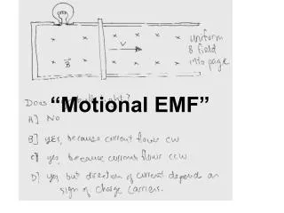
“Motional EMF”. A= I, B= ii, C=iii. Clockwise zero. What is the direction of the magnetic field produced by this current loop inside the loop? A] upward B] downward. I is CW from above. B. Note the splay in the field lines!. Viewed from above, current in the loop A] will flow clockwise

“Motional EMF”
E N D
Presentation Transcript
A= I, B= ii, C=iii. Clockwise zero
What is the direction of the magnetic field produced by this current loop inside the loop?A] upwardB] downward I is CW from above B
Note the splay in the field lines! Viewed from above, current in the loop A] will flow clockwise B] will flow counterclockwise C] will not flow at all A
Consider vxB. Since the field lines splay, vxB is CW from above. The current in the loop causes a downward B field inside the loop. The flux of this induced B field Opposes the flux change that would otherwise occur. “Lenz’s Law” Induced current is CW, seen from above, by RHR.
Viewed from above, current in the loop A] will flow clockwise B] will flow counterclockwise C] will not flow at all
The flux through the loop is downward and decreasing. To oppose this change, we need the current in the loop to flow CLOCKWISE, seen from above. (Again, if the loop is moving, you can use vxB to find the direction of the force. But you have to remember that the field lines are getting farther apart farther from the magnet.)
We saw that, when we move the loop down, a CW current flows, owing to the B field acting on the (downward moving) charges. If, instead, we move the magnet UP, keeping the loop still, current: A] will flow clockwise (viewed from above) B] will flow counterclockwise C] will not flow all, since B fields don’t act on stationary charges.
While it’s true that B fields don’t act on stationary charges, it really shouldn’t matter which object is moved! Let’s do the experiment!
Changing magnetic fields DO result in the motion of stationary charges. Thus, changing magnetic fields must “induce” electric fields. (It is perhaps better to say that changing magnetic fields are “coupled to” electric fields….)
What can we say about the induced E field? Like with Ampere’s law, we can only find E from this easily when there is A LOT of symmetry. E must (by symmetry) be the same everywhere, or zero, in our loop. (In cases without symmetry, there is still an E field; we just don’t have the math tools to find it.)
Examples where we can “easily” find E from a changing magnetic field. Circular loop, N pole of magnet, with change of flux specified. A very long (infinite) solenoid, with ramping current (and B field)
A loop of copper wire is shown. Moving the magnet up: A] causes increasing upward B flux B] causes decreasing upward B flux C] causes decreasing downward B flux D] causes increasing downward B flux E] has no effect on the flux through the loop
A loop of copper wire is shown. Moving the magnet up -causes increasing upward B flux. In what direction should the B field caused by the induced current be? A] up B] down
A loop of copper wire is shown. Moving the magnet up -causes increasing upward B flux. The loop current should oppose the flux change. So the field from the loop current should be DOWN. What direction does the current flow, viewed from above? A] CW B] CCW
A loop of copper wire is shown. Moving the magnet up -causes increasing upward B flux. The loop current should oppose the flux change. So the field from the loop current should be DOWN. The induced current must flow CW, seen from above, by the RHR.
What is the direction of the induced current in the ring, as seen from above? A] CW B] CCW C] There is no induced current A
Considering the magnetic field of the solenoid as a magnet: The top of the solenoid is a A] N B] S pole A
Considering the magnetic field of the loop as a little magnet: the North pole of the loop is A] up B] down B
The magnetic force between the solenoid and the coil should be A] attractive B] repulsive C] zero B
Generators At this instant, current through the light bulb will flow: A] left to right in side view B] right to left in side view C] not at all A
Generators At this instant, current through the light bulb will flow: A] top to bottom in side view B] bottom to top in side view C] not at all C
Let’s do the math for a rotating loop in a uniform B field. B
More about motional EMF A square loop is pulled through a constant B field. What is the magnitude of the motional emf? A] 0 B] vBL C] 2vBL D] vBL2 A
More about motional EMF Although there is magnetic flux through the loop, the amount is NOT changing with time. So emf = 0.
Here, the left side is not moving, so there is no magnetic force on the initially stationary charges on that side. There is magnetic force on the charges on the right side, pushing positive charges up. Each charge acquires an energy = qvBL = force x distance. That energy is then lost as the charge “slides downhill”, through the lightbulb, heating it. Where does the energy come from that lights the bulb? It cannot come from the B-field, as that is unchanging while the bar is sliding. Answer: you must use force to pull the right side at constant v. How much force?
More on Solenoids Long solenoids have spatially uniform B inside (from Ampere’s law) If the current is increased linearly with time, the B field will increase linearly with time. In this case, the field is out of the page (top view) and increasing with time. If this is done, what will be the direction of the induced E field at point b, distance r from the axis? On the top view: A] up B] down C] left D] right E] out of the page B
More on Solenoids Consider a loop at a radius r. The flux is upward and increasing, so the induced EMF must be such as to cause a downward B field if a loop of wire were there. So the EMF must be CW (from above) and E must point downward (top view.) Let’s do the math….
More on Solenoids What is the induced E field at point a, on the solenoid axis? A] 0 B] not zero A
More on Solenoids What is the induced E field at point c, outside the solenoid, where B is essentially zero? A] 0 B] not zero, upward (top view) C] not zero, downward (top view) D] not zero, leftward(top view) .c B
Now consider 4 loops, all with the same area. The B field is increasing with time. What is true? A] loops a,b,c have the same , but d has less. B] loops a and c have =0, but b and d have same nonzero . C] loop a has =0, but b,c,d have the same, nonzero . D] loop c has =0, loop a has a little, b has more, and d the most. E] loop c has =0, but loops a,b,d all have the same nonzero . E
Resistor: opposes “motion” (current), like friction Inductor: opposes change in motion, like inertia
Do not confuse “cause” and “effect”. The voltage drop from a to b (in part c) is an effect of the increasing current. Something has to “overcome” (meaning provide) this voltage drop if the current is to increase. Think of the “back EMF” this way: if you replace the inductor with a battery, the battery (by itself) would drive current that would oppose the change.
Immediately after closing the switch, where is the potential higher?A] AB] BC] Potential at A& B is the same A
A very long time after closing the switch, where is the potential higher?A] AB] BC] Potential at A& B is the same C
After the switch has been closed a long time and a steady state reached, the switch is opened. Where is the potential higher?A] AB] BC] Potential at A& B is the same B
Archuleta C Herrera Es Martinez Middleton Sinyenko Warren Wildau Wed Dec 1, 2010 Which curve shows the current after switch s1 is closed? B Let’s calculate…
Which curve shows the voltage drop across the inductor after S1 is closed? C
Which curve shows the voltage drop across the resistor after S1 is closed? B
After reaching a steady current, S1 is opened and S2 is closed, simultaneously. What curve shows the voltage drop (from a to b) across the resistor vs time? C
After reaching a steady current, S1 is opened and S2 is closed, simultaneously. What curve shows the voltage drop (from b to c) across the inductor vs time? D
A little while (t=L/2R) after the switch is closed, what is the voltage around the circuit? C
What is the voltage around the circuit a long time after the switch is closed? B
Switch s1 is closed. Just after, what is the current through the resistor? A A] 0 B] E/R C] E/(RL) D] E/(RC)
Just after closing switch S1, what is the voltage drop across the inductor? B A] 0 B] E C] E/2 D] E/L
A long time after closing switch S1, what is the charge on the capacitor? B A] 0 B] CE C] E/C D]E/(RC)
Ampere’s law This completes “Maxwell’s Equations”