Download
1 / 74
740 likes | 873 Vues
The Plant Control Design Handbook (PCDH) v6 provides essential methodologies, standards, specifications, and interfaces tailored for the ITER (International Thermonuclear Experimental Reactor) plant systems integrating Instrumentation and Control (I&C). This release emphasizes the importance of standardization in ensuring seamless operation through a structured control system, vital for managing interactions and mitigating potential issues during construction. The document also highlights the I&C life cycle, components of control systems, and the role of interlocks and safety controls, ensuring personnel safety and environmental protection.

E N D
PCDH v62011 release • Why to standardize, PCDH ? • Overview of ITER I&C • ITER standards for I&C • Interlock and Safety controls • I&C life-cycle and illustration • PCDH v6 status and v6/v5
PCDH v62011 release • Why to standardize, PCDH ? • Overview of ITER I&C • ITER standards for I&C • Interlock and Safety controls • I&C life-cycle and illustration • PCDH v6 status and v6/v5
This is the ITER Agreement 140 PA’s 80 include I&C
But this will work only if… …all these links work
That is why we, CODAC team, concentrate all our effort on standards (PCDH) and implementation of those standards (CODAC Core System) • What is PCDH? • Plant Control Design Handbook (PCDH) defines methodology, standards, specifications and interfaces applicable to all ITER plant systems I&C. • PCDH is an annex to Project Requirements (PR) and applicable to all Procurement Arrangements with I&C. • PCDH is released at regular interval throughout the construction phase of ITER. • PCDH is reviewed by I&C IPT.
PCDH v6 scope Master document • Master document: (27LH2V v6.1) • ITER baseline document, • Provides all rules, is contractually binding, • Is summited to PCR
PCDH v6 scope Satellite documents Satellite documents: Provide guidelines, recommendations and explanations, but no mandatory rules.
PCDH v62011 release • Why to standardize, PCDH ? • Overview of ITER I&C • ITER standards for I&C • Interlock and Safety controls • I&C life-cycle and illustration • PCDH v6 status and v6/v5
Three vertical tiers, two horizontal layers I&C structure Segregation of ITER I&C into 3 vertical tiers and 2 horizontal layers Conventional Control Control and monitoring for all ITER PS Interlock Protects the investment Independent network and I&C Safety Protects personnel, and environment Independent network and I&C Two train systems
Finite set of “Lego blocks”, which can be selected and connected as required
Plant System I&C is a deliverable by ITER member state (procurement arrangement). Set of standard components selected from catalogue.
ITER Subsystem is a set of related plant system I&C.
Plant System Host is an IO furnished hardware and software component installed in a Plant System I&C cubicle. There is one and only one PSH in a Plant System I&C. PSH is mainly used to interface the PS I&C with CODAC
Slow Controller is a Siemens Simatic S7 industrial automation Programmable Logic Controller (PLC). There may be zero, one or many Slow Controllers in a Plant System I&C. A Slow Controller runs software and plant specific logic programmed on Step 7 and interfaces to either PSH or a Fast Controller using IO furnished interface. A Slow Controller has normally I/O and IO supports a set of standard I/O modules. A Slow Controller has no interface to HPN. A Slow Controller synchronizes its time using NTP over PON. A Slow Controller can act as supervisor for other Slow Controllers.
Fast Controller is a dedicated industrial controller implemented in PCI family form factor and PCIe and Ethernet communication fabric. There may be zero, one or many Fast Controllers in a Plant System I&C. A Fast Controller runs RHEL and EPICS IOC. It acts as a channel access server and exposes process variables (PV) to PON. A Fast Controller has normally I/O and IO supports a set of standard I/O modules with associated EPICS drivers. A Fast Controller may have interface to High Performance Networks (HPN), i.e. SDN for plasma control and TCN for absolute time and programmed triggers and clocks. Fast Controllers involved in critical real-time runs a RT enabled (TBD) version of Linux on a separate core or CPU. A Fast Controller can have plant specific logic. A Fast Controller can act as supervisor for other Fast Controllers and/or Slow Controllers. The supervisor maintains Plant System Operating State. Not relevant for PBS 43-62-63-65
High Performance Computer are dedicated computers (multi core, GPU) running plasma control algorithms. Not relevant for PBS 43-62-63-65
High Performance Networks are physically dedicated networks to implement functions not achievable by the conventional Plant Operation Network. These functions are distributed real-time feedback control, high accuracy time synchronization and bulk video distribution. Not relevant for PBS 43-62-63-65
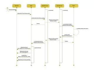
Simplest possible Plant System I&C – Data flow CODAC System / Mini-CODAC send commands and, if required, publish data from other Plant System I&C to PSH using channel access protocol PSH receives absolute time from TCN (4). The absolute time on the Slow Controller can be set using NTP with PSH as NTP server PSH publish data, alarms and logs to CODAC System / Mini-CODAC using channel access protocol. PSH and Slow Controller exchange data using standard interface provided by IO (3) The Slow Controller interfaces via signal interface to actuators and sensors and contains plant specific software and logic programmed on Step 7
Simple Mixed Plant System I&C – Data flow CODAC System / Mini-CODAC may send commands and, if required, publish data from other Plant System I&C to Fast Controller using channel access protocol (6). Fast Controller may publish data, alarms and logs to CODAC System / Mini-CODAC using channel access protocol (7) PSH supervises Fast Controller (8) to manage COS Fast Controller could interface directly to Slow Controller using standard interface provided by IO (9) or indirectly through PSH by (8) and (3) Not relevant for PBS 43-62-63-65 SD: Plant System I&C Architecture (32GEBH v2.3)
PCDH v62011 release • Why to standardize, PCDH ? • Overview of ITER I&C • ITER standards for I&C • Interlock and Safety controls • I&C life-cycle and illustration • PCDH v6 status and v6/v5 • Slow controllers • Fast controllers • I&C cubicles • Signals
ITER slow controllers: Selected products Next rack Next rack Medium range PLCs S7-300 High range PLCs S7-400 Fail safe SIL3 and high availability PLCs I/O interfaces are the same for high and medium ranges PLCs (ET200 products), only CPU and CPU chassis differ. I/O interfaces, CPUs and chassis are specific to this product line.
ITER slow controllers: a large range of configurations for flexibility Configuration 1 The simplest configuration with I/O cards within the S7-300 CPU rack Configuration 2 Generic architecture with remote IO racks connected in serial architecture. Configuration 3 Both serial and star configuration may be mixed. switch Next Rack Next Rack
ITER slow controllers: Network and software development • Networks • Ethernet 100 Mbits/s for S7 CPU to CODAC front-ends. • PROFINET V2 for process interface within the S7. • IEC 61850 for communication with equipments of power stations. • Profisafe profile over Profinet for SIL-3 purposes. • Software development • STEP 7 Professional version for user software development. • Additional function block options if required for the plant system. • Guidelines for software development included in PCDH v6. SD: Siemens S7 PLC Catalogue (333J63 v1.7)
ITER slow controllers: e-ordering: implementation process Siemens S7 PLC Ordering process (3Q6UQ3 v1.0)
ITER fast controllers: I/O Bus and Industrial Form Factors • PCDH defines CODAC selection for I/O bus: • PCI bus (parallel) • PCI-Express (serialized, PCI functions as payload) • PCDH defines CODAC selection of communication method for interconnected systems: • Ethernet • The definition covers extremely large selection of different industrial computers and form factors • CODAC Standards include and full support is given to: • Conventional PCI and PCI Express boards • PICMG 1.3 SHB industrial computers • PXI Express hybrid chassis forPXI, CompactPCI and PXI Express I/O boards • ATCA shelf and blades for high end data acquisition Not relevant for PBS 43-62-63-65
6U CompactPCI Digitizer (not in catalogue) Conventional PCI / cPCI Bus Extension 1 Gb/s Ethernet • 4U PICMG 1.3 chassis • High-end CPU (2 x Xeon) Bus Extension PCI-Express x4 - PXIe Chassis (hybrid) I/O : - PXI / PXI Express - CompactPCI ITER fast controllers: PCI Express for modularity and interoperability Connecting together different form factors of PCI and PCI Express based systems Not relevant for PBS 43-62-63-65 10 Gb/s Ethernet Read More SD: Guideline for Fast Controllers (333K4C v1.3)
1 Gb/s Ethernet 2U PICMG 1.3 chassis Optional10 Gb/s Ethernet Bus Extension PCI-Express x1 PXIe Chassis I/O - PXI - CompactPCI - PXI Express ITER fast controllers: Basic Fast Controller Configurations and Ideas • Separation in different physical units: • CPU, network and – in some cases – solid state disks • I/O cards and cabling • Example:Simple,generalpurposeFastController Not relevant for PBS 43-62-63-65 SD: ITER Catalogue of I&C Products – Fast Controllers (345X28 v1.3)
ITER I&C cubicles configurations Configuration1: The I/O interfaces of the I&C controllers are connected to PSEs through signal conditioning interfaces housed in an SCC. Configuration2: This configuration is similar to configuration 1, but LCC and SCC are merged in order to optimise the space allocation.
ITER I&C cubicles configurations Configuration3: In this configuration, the I&C controller of LCC is configured with a remote I/O rack installed in the SCC. The link between the LCC controller and the remote I/O rack may be fibre optic in the case of a long distance connection, strong EMI issues or any voltage isolation issue. Preferred configuration for Tokamak building. Configuration4: In this configuration, the PSE are connected to the I&C controller by a plant system I&C field-bus. The medium may be fibre optic. Targets for cubicle standardization: All LCCs and SCCs cubicles whatever the plant system.
ITER I&C cubicles Selected products SD: SAREL cubicle catalogue for plant system I&C (35LXVZ v2.3) e- configuration: http://www.iter-schneider-electric.com/
Signal interfaceScope PCDH • IO cabling rules, (335VF9) • IO cable catalogue (355QX2) • ITER EMC policy (42FX5B)
Signal interfaceSignal standards • Sensors • Voltage range: 0V to +10V unipolar, -5V to +5V bipolar, -10V to +10V bipolar. • Current range: 4mA to 20mA (16mA span). Signal polarity: positive with respect to signal common. • Actuators • Output Current: 4mA to 20mA (16mA span). Signal polarity: positive with respect to signal common. Load resistance: 500 max. Preferred 250 . • Output voltage: 0V to +10V unipolar or: -10V to +10V bipolar. • Digital signals • Signal logic: positive for process control, negative for fail safe logics. • Range: 24V DC referenced to plant system I&C cubicle earth. Maximum current depends on the galvanic isolation interface. • T sensors • Resistance thermometers: Pt100, 4 wires. • Thermocouples: type K, type N. • A passive low-pass input filter may be recommended for any T sensor. • Pneumatic signals • Range: 0.2 to 1 bar for the current / pressure converters of the pneumatic proportional control valves. • 0 to 6-8 bars for the non proportional control valves.
Signal interfaceEMC policy • Single point earthing: For the Cryostat, the concept of single-point earthing has been selected and a loop Exclusion Zone (LEZ). Multipoint earthing: For other locations outside LEZ. Apply IEC 61000-5-2. • Signal transmission schemes are proposed for each signal type. Sensor configuration with differential amplifier at receiver level Sensor configuration with full differential configuration SD: I&C signal interface (3299VT v4.4)
PCDH v62011 release • Why to standardize, PCDH ? • Overview of ITER I&C • ITER standards for I&C • Interlock and Safety controls • I&C life-cycle and illustration • PCDH v6 status and v6/v5 • Naming convention • Software engineering • HMI and alarm handling • Common Operating States
Naming convention for variables 1/2 Signal Name = PS Component Identifier : Signal Identifier Variable Name = PS Function Identifier : Variable Identifier • Component identifier: ITER naming convention applies. • Signal identifier: ITER naming convention based on ISA applies. • Variable identifier: only guidelines are proposed by ITER, see SW HB
Naming convention for variables 2/2 SD: Signal and plant system I&C variable naming conventions (2UT8SH v7.3)
Software development guidelines • SD: Software Engineering and Quality Assurance (2NRS2K v2.1) • SD: PLC software engineering handbook (3QPL4H v1.3) • PLC user software engineering: • Software architecture. • Coding language. • Templates. • Conventions • Targets are interfaces mainly.
Human Machine Interface RD: (operation) ITER Human Factor Integration Plan (2WBVKU v1.1) SD: Philosophy of ITER Operator User Interface (3XLESZ v2.0) • Operator User Interface Principles: • Operator Tasks Analysis. • Operator User Interface Detailed Design: • Implementation. • Operator User Interface Testing. • Training. Expected: user manuals for HMI
Alarm handling RD: ITER Human Factor Integration Plan (2WBVKU v1.1) SD: Philosophy of ITER Alarm System Management (3WCD7T v2.0) • What is an Alarm? • Alarm management lifecycle. • Alarm philosophy principles. • Key Design Principles for the alarm system. • Alarm for redundant components. • Alarms in case of dependant failures. • Alarm Engineering Checklist. • Rationalisation of the alarm system. • Detailed Design of the alarm system. Expected: user manuals for alarm handling
COS: alignment with Operation Handbook RD: Operations Handbook – 2 Operational States (2LGF8N v1.2).