Download
1 / 31
330 likes | 649 Vues
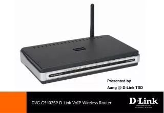
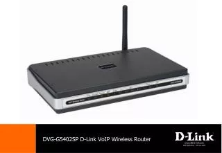
DVG-G5402SP D-Link VoIP Wireless Router. www.dlink-intl.com DRS Marketing – 02 Jan 2008. Agenda. Product Overview DVG-G5402SP Key Features Hardware Description Web GUI Site Map DVG-G5402SP Setup Internet Set up with Cable Modem Setting Up Wireless SSID & Security

E N D
DVG-G5402SP D-Link VoIP Wireless Router www.dlink-intl.com DRS Marketing – 02 Jan 2008
Agenda Product Overview • DVG-G5402SP Key Features • Hardware Description • Web GUI Site Map DVG-G5402SP Setup • Internet Set up with Cable Modem • Setting Up Wireless SSID & Security • Setting Up Wireless MAC filtering • Save and Reboot Troubleshooting • Device Status & Statistics • Reset Factory Default Questions and Answers
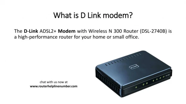
Product Overview • The DVG-G5402SP is designed to carry both voice and fax over the IP network and wirelessly share Internet access. • It uses the industry standard SIP call control protocol so as to be compatible with free registration services or VoIP service providers’ systems. As a standard user agent, it is compatible with all common Soft Switches and SIP proxy servers. • The DVG-G5402SP can be seamlessly integrated into an existing network by connecting to a phone set and fax machine. With only a broadband connection such as an ADSL bridge/router or a Cable Modem, the VoIP Router allows you to use voice and fax services over IP in order to reduce the cost of all long distance calls. • The DVG-G5402SP is also an 802.11b/g wireless access point. Allow wireless clients to connect to it and share your broadband Internet connection. A built-in 4-port switch makes it possible to connect up to 4 Ethernet-enabled computers or devices to also share your Internet connection.
DVG-G5402SP Key Features Internet Telephone 2 FXS Ports for Phones+1 PSTN (Life Line) SIP Protocol Convenient Call Feature Support Guaranteed Voice Quality With QoS WAN/LAN Connection 10/100Mbps Ethernet WAN Port 4 10/100Mbps Ethernet LAN Ports 802.11g WLAN (Up to 54Mbps Wireless Speed) PPPoE Dial-Up Broadband Support Page 4
DVG-G5402SP Key Features Built-in Router • DHCP Server for Automatic IP Assignment • IP Sharing for Multiple Users Internet Access Via Single IP (NAT) • IPSec/PPTP VPN Pass-Through Configuration/Management • Easy Installation With GUI Support • Auto provisioning Using TFTP Encryption/ Authentication • Remote Firmware Update via TFTP/FTP/HTTP
Hardware Description – Front Panel • Power: Power LED. A steady light indicates a proper connection to a power source. • Prov./Alm.: A blinking light indicates the VoIP Router is attempting to connect with the Provisioning server. Once the service connects, the LED will turn off. The LED will light solid if the self-test or boot-up fails. • Register: The Register LED will turn on when the VoIP Router is connected to a VoIP service provider. The LED will be blinking if not connected to a service provider. • WAN: When a connection is established the 10 or 100 LED will light up solid. The LED will blink to indicate Page 7
Hardware Description – Front Panel • WLAN: A steady light indicates a wireless connection. A blinking light indicates that the VoIP Router is receiving/transmitting from/to the wireless network. • LAN: When a connection is established the 10 or 100 LED (bottom) will light up solid on the appropriate port. The LEDs will blink to indicate activity. If the 10 or 100 LED does not light up when a cable is connected, verify the cable connections and make sure your devices are powered on. • Phone: This LED displays the VoIP status and Hook/Ringing activity on the phone port that is used to connect your normal telephone(s). If a phone connected to a phone port is off the hook or in use, this LED will light solid. When a phone is ringing, the indicator will blink. • Line: Light on means the line is in use (off-hook), and vice versa. Page 8
Hardware Description – Rear Panel • Line: Connect to your original telephone line on the wall jack with RJ-11 cable. • Phone Port (1-2): Connect to your phones using standard phone cabling (RJ-11). • LAN: Connect to your Ethernet enabled computers using Ethernet cabling. • WAN: Connect to your broadband modem using an Ethernet cable. • Power Receptor: Receptor for the provided power adapter. • Ground: A conducting connection with the earth. Connect with the ground so as to make the earth a part of an electrical circuit using metal wire. • Antenna: Connect to a wireless network. WARNING: DO NOT (1) connect the phone ports to each other (FXS to FXS) or (2) connect any phone port directly to a PSTN line (FXS to PSTN) or to an internal PBX line (FXS to PBX extension). Doing so may damage your VoIP Router. Page 10
Web GUI Site Map Page 12
Setting Up DVG-G5402SP DVG-G5402SP Step 1. Please ensure that the cable modem is power off. Connect the Ethernet cable from the WAN port of DVG-G5402SP to the cable modem. Then connect the Ethernet cable from your PC into any of the LAN ports on the DVG-G5402SP LAN Port WAN Port Analog Phone Cable Modem PC Page 13
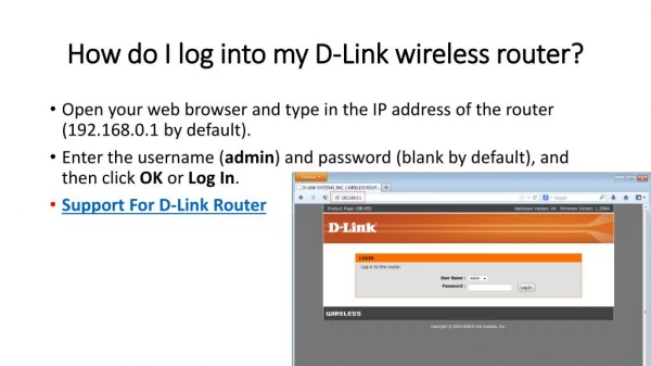
Setting Up DVG-G5402SP Step 2. Next, power up the cable modem first followed by the router. Step 3. Open up a web browser and enter http://192.168.8.254 in the address\URL field. You will see the log in page. Type “User” as the user name and leave the password field empty. Click on the “Login” button. Page 14
Setting Up DVG-G5402SP Step 4. Select “Setup” tab from the navigation menu and click on “Internet Setup”. Internet Connection type should be selected as “DHCP” and “Auto” for DNS server. Page 15
Setting Up DVG-G5402SP Step 5. Select “Status” tab from the navigation menu and click “Device Info” Step 6. Check the “WAN Port Information” section to see if you have obtained a DHCP IP address and DNS leased from the cable modem successfully. Page 16
Setting Up SSID on DVG-G5402SP Step 1. Select “Setup” tab from the navigation panel and click on “Wireless Setup”. Then, Click on “Wireless Basics” to configure basic wireless setting. Page 17
Setting Up SSID on DVG-G5402SP Step 2. Change the default “Wireless Network Name(SSID)” from “DVG-G5402SP to “SHxxxxxxx,” where xxxxxxx is the customer’s StarHub account number. Step 3. Choose “Wireless Channel” to specified channel (Auto Scan Mode is recommended in order to avoid channel interference Step 4. 802.11 Mode can be set as 802.11b Only or 802.11g Only or Mixed Mode. Step 5. Click “Apply” button to save the changes. Page 18
Setting Up Wireless Security Step 1. Select “Setup” tab from the navigation panel and click on “Wireless Setup-> Wireless Security” to configure wireless security setting Page 19
Setting Up Wireless Security Step 2. Select the encryption/authentication type: None, WEP, WPA, WPA2 and WPA2 Mixed. Step 3. Refer to the manual for detail configuration of each security mode Page 20
Setting Up Wireless MAC filtering Note: MAC filtering applies to the computers connected wirelessly. Make sure you had keyed in the correct MAC Address to prevent locking yourself out of the router Step 1. Select “Advanced” tab from the navigation panel and click on “Advanced Wireless”. Then, Click on “Access Control” button to create MAC filter list Page 21
Setting Up Wireless MAC filtering Step 2. From the drop down menu of “Access Control Mode”, select the option “Allow”. When Allow Listed is enabled, only those wireless clients whose MAC addresses are in the Access Control List have rights to connect to the device Step 3. In order to add the MAC address which you want to allow/deny access DVG-G5402SP, Click on the “Add” button. Page 22
Setting Up Wireless MAC filtering Step 4 To know your PC’s Wireless adapters MAC address, click on Start Run and enter CMD and Click on “OK”. On the DOS windows type “ipconfig /all”. You will see the MAC addresses of wireless adaptor. Key in the MAC address listed into the “MAC Address” field. Page 23
Setting Up Wireless MAC filtering Step 5. Enter the MAC address of the specified PC in the MAC field with xx:xx:xx:xx:xx:xx format. Step 6. Click “Apply” to add the MAC address to the Wireless Access Control list. Page 24
Setting Up Wireless MAC filtering Step 7. The desired MAC address will now be in the “MAC Address” field as shown in the example depicted below. Step 8. In order to save and activate the new settings, Click “Save & Restart” Otherwise, select “Maintenance” tab and click on “Backup and Restore” menu. Page 25
Save and Reboot the DVG-G5402SP Step 1. Click the “Save All Settings”check box and click on “Reboot” so that the new settings will take effect after the VoIP Router is restarted. Step 2. Press the “OK” button if “Reboot Device?” popup box come out. Page 26
Troubleshooting Hardware problems: • Off hook and on hook a port, check if LED state changes • FXS port should give tones while off hooked • Check WAN and LAN LED to map your real connection • ping from PC, ping to PC, ping to Router, ping DNS Server Software configuration problems: Check “STATUS \ VoIP Status” page for SIP registration result, port state, and “STATUS \ Device Info” for WAN and LAN information. Always check if gateway has a correct WAN IP address allocated! Page 27
Device Status – Device Info Page 28
Device Status – VoIP Status The status on this page reflect the VoIP telephone number and Registration Status of SIP Account. Page 29
Device Status – RTP Statistics Codec type, no of RTP packet sent and received, no of packet lost for each phone line can be seen on this page. Page 30
Restore Default Setting Method 1: Select “Restore Default Settings” under “MAINTENANCE-> Backup and Restore” to reset the VoIP Router’s settings back to the factory default settings via Web UI. Method 2: Use Reset Button to restore factory default settings: 1. Power on. 2. Press and hold the reset button for 5 seconds. 3. Release the reset button. Factory settings will be restored. Page 31