Guide to EM Waveguiding: Principles and Examples
Learn about EM waveguides, modes, reflection, propagation, dispersion, cutoff frequency, boundary conditions, and comparison of TE and TM modes.

Guide to EM Waveguiding: Principles and Examples
E N D
Presentation Transcript
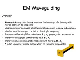
EM Waveguiding Overview • Waveguidemay refer to any structure that conveys electromagnetic waves between its endpoints • Most common meaning is a hollow metal pipe used to carry radio waves • May be used to transport radiation of a single frequency • Transverse Electric (TE) modes have E┴kg (propagation wavevector) • Transverse Magnetic (TM) modes have B┴kg • Transverse Electric-Magnetic modes (TEM) have E, B┴kg • A cutoff frequency exists, below which no radiation propagates
EM Waveguiding Electromagnetic wave reflection by perfect conductor E┴can be finite just outside conducting surface E|| vanishes just outside and inside conducting surface EI EI┴ D┴1= D┴2 ER EI┴ ER┴ ER┴ EI|| ER|| qr qi D┴1 = eoE┴1 - - - - - - - y y D┴2 = eoeE ┴2 E||1 = E||2 z z EoI+ EoR = 0 EI|| EI|| EI|| ER|| ER|| ER|| y EoT= 0 z
EM Waveguiding Electromagnetic wave propagation between conducting plates Boundary conditions B┴1= B┴2 E||1 = E||2 (1,2 inside, outside here) E|| must vanish just outside conducting surface since E = 0 inside E┴ may be finite just outside since induced surface charges allow E = 0 inside (TM modes only) B┴ = 0 at surface since B1 = 0 Two parallel plates, TE mode k2 E2 E1 k1 x z b y q b
EM Waveguiding E = E1 + E2 = exEoeiwt (ei(-kysinq + kzcosq) - ei(kysinq + kzcosq)) = exEoeiwte-ikzcosq2i sin( kysinq) Boundary condition E||1 = E||2 = 0 means that E = E||vanishes at y = 0, y = b E||(y=0,b) if ky sinq= np n = 1, 2, 3, .. Fields invacuum E1= exEoei(wt - k1.r) k1= -eyk sinq + ez k cosq k1.r= -kysinq+ kzcosq E2= -exEoei(wt - k2.r) k2= +eyk sinq + ez k cosq k2.r= +ky sinq + kzcosq
EM Waveguiding Allowed field between guides is E = exEoeiwte-ikzcosq2i sin( kysinq) = exEoeiwt e-ikzcosq2isin(npy/b) Since The wavenumber for the guided field is kg = k cosqn = 1, 2, 3, .. Profile of the first transverse electric mode (TE1) Fields E1= exEoei(wt - k1.r) k1= -eyk sinq + ez k cosq k1.r= -kysinq+ kzcosq E2= -exEoei(wt - k2.r) k2= +eyk sinq + ez k cosq k2.r= +ky sinq + kzcosq Ex sin(npy/b) y
EM Waveguiding Magnetic component of the guided field from Faraday’s Law x E = -∂B/∂t = -iwB for time-harmonic fields B= i x E /w = 2Eo / w(0, ikgsin(npy/b), √(- kg)cos(npy/b) )ei(wt - kgz) The BC B┴1 = B┴2 = 0 is satisfied since By = 0 on the conducting plates. The E and B components of the field are perpendicular since Bx = 0. The phase velocity for the guided wave is vp = w / kg = c k / kg kg = Hence vp= c The group velocity for the guided wave is vg = ∂w/ ∂kg= c ∂k/ ∂kg = c kg/k vpvg = c2
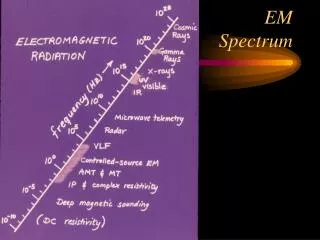
EM Waveguiding Frequency Dispersion and Cutoff cutoff when → 1 w= ck = 2pn n = = ncutoff= kg== b b q q’ 2 modes 1 propagating mode kg vacuum propagation
EM Waveguiding Summary of TEn modes E= 2 Eo(i sin(npy/b), 0 ,0) ei(wt - kgz)kg= B= 2Eo / w(0, ikg sin(npy/b), √(- kg)cos(npy/b) )ei(wt - kgz) Phase velocity vp = w / kg = c k / kg E B Group velocity vg= ∂w/ ∂kg= c kg/ k ncutoff,n = = x x y y viewed along kg
EM Waveguiding Electric components of TEn guided fields viewed along x (plan view) n = 1 n = 2 n = 3 n = 4 Magnetic components of TEnguided fields viewed along x (plan view) z z y y
EM Waveguiding Rectangular waveguides Boundary conditions B┴1 = B┴2 E||1 = E||2 E|| must vanish just outside conducting surface since E = 0 inside E┴ may be finite just outside since induced surface charges allow E = 0 inside B┴ = 0 at surface Infinite, rectangular conduit 0 a x z y b
EM Waveguiding TEmn modes in rectangular waveguides TEn modes for two infinite plates are also solutions for the rectangular guide E field vanishes on xz plane plates as before, but not on the yz plane plates Charges are induced on the yz plates such that E = 0 inside the conductors Let Ex = C f(x)sin(npy/b) ei(wt- kgz) In free space .E= 0 and Ez= 0 for a TEmnmode and ∂Ez/∂z = 0 Hence ∂Ex/∂x = -∂Ey/∂y f(x) = -np/ b cos(mpx/a) satisfies this condition • By integration • Ex= -C np / b cos(mpx/a) sin(npy/b) ei(wt - kgz) • Ey= C mp / a sin(mpx/a) cos(npy/b) ei(wt - kgz) • Ez = 0
EM Waveguiding Dispersion Relation Substitute into wave equation(2 - 1/c 2 ∂ 2/∂t2 )E= 0 2Ex,y =Ex,y ∂ 2/∂t2Ex,y = - w2Ex,y - w2/ c2 = 0 kg = Magnetic components of the guided field from Faraday’s Law Bx = -C mp / a / wsin(mpx/a) cos(npy/b) ei(wt - kgz) By= -C np/ b / wcos(mpx/a) sin(npy/b) ei(wt - kgz) Bz= iC√) / w cos(mpx/a) cos(npy/b) ei(wt - kgz)
EM Waveguiding Cutoff Frequency kg = ncutoff=
EM Waveguiding Electric components of TEmn guided fields viewed along kg m = 0 n = 1 m = 1 n = 1 m = 2 n = 2 m = 3 n = 1 Magnetic components of TEmnguided fields viewed along kg x x y y
EM Waveguiding Comparison of fields in TE and TM modes www.opamp-electronics.com/tutorials/waveguides_2_14_08.htm
EM Waveguiding The TE01 mode Most commonly used since a single frequency ncutoff,02 > n >ncutoff,01 can be selected so that only one mode propagates. Example 3 cm radar waves in a 1cm x 2 cm guide ncutoff,01= c = 7.5 x 10⁹ Hz ncutoff,01= c = 7.50 x 10⁹ Hz ncutoff,10= c = 1.50 x 10¹⁰ Hz ncutoff,11= c = 1.68 x 10¹⁰ Hz