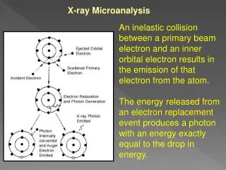
Electron Optics Two essential components:
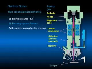
Electron gun Cathode Anode Alignment coils. Lenses condensers objective. Objective aperture assembly. Electron Optics Two essential components:. Electron source (gun) Focusing system (lenses) Add scanning apparatus for imaging. sample. → → →. F = -e(VxB).

Electron Optics Two essential components:
E N D
Presentation Transcript
Electron gun Cathode Anode Alignment coils Lenses condensers objective Objective aperture assembly Electron Optics Two essential components: • Electron source (gun) • Focusing system (lenses) • Add scanning apparatus for imaging sample
→ → → F = -e(VxB) Electron Lenses Principle of electromagnetic focusing Interaction of electromagnetic field on moving charge (electron) Vector equation F = Force on electron V = electron velocity B = Magnetic field strength (rotationally symmetric) e = charge of electron Magnitude of F will be F = -eVBsinθ where θ is the smaller of two angles between V and B Direction of F determined by “right hand rule”
Axially symmetric electromagnetic lens Fe shielding to prevent flux leakage from solenoid Lens strength: intensity of field in gaps proportional to (NxI) N = # turns of solenoid winding I = current flowing through windings
High lens strength = short focal length f f Low lens strength = long focal length Focal Length (f): Point on Z axis where initially parallel rays cross the axis after passing through the lens HIGHER LENS STRENGTH = SHORTER FOCAL LENGTH B = vector parallel to field Br = radial component of field (vector perpendicular to axis) Bz = axial component of field (vector parallel to axis) B varies depending on position in lens Upper polepiece Results: Force strongest in the center of the gap Actual electron paths spiral through lens Lower polepiece
Usually two-stage condenser system • Purpose: • Further demagnification of the gun crossover image • Control amount of beam entering objective • major effect on beam current at sample • High Lens strength • Small crossover image • Less current entering the objective • Low Lens strength • Large crossover image • More current entering the objective
f (high condenser lens strength) f (low condenser lens strength) Electron gun Condenser Objective High condenser strength Short focal length Large divergence angle Low current into objective Low condenser strength Long focal length Small divergence angle High current into objective Sample
Objective lens Purpose: control the size and shape of the final beam spot Considerations: Produce small beam diameter Magnetic field must not hinder detector system from collecting low eV electrons Must allow clear path from sample to detectors Bore must be large Contain scan coils and Stigmators Beam-limiting apertures Aberrations usually increase with focal length – minimize aberrations For quantitative analysis long focal length = long working distance high takeoff angle and low absorption
For objective Increase demagnification by increasing lens strength to produce small spot size → Short working distance due to short focal length → Short depth of field Objective lens, therefore, Controls image focus = beam size
Pinhole lens Objective lens design Immersion lens Snorkel lens
f (high objective lens strength) = short working distance f (low objective lens strength) = long Working distance Effective beam diameter Electron gun Condenser High objective strength Short focal length Large divergence angle Short working distance Short depth-of-field High resolution Low objective strength long focal length Small divergence angle Long working distance Large depth-of-field Low resolution Objective Sample
Current in final beam spot is a function of: • Condenser lens strength • Objective aperture size • Objective aperture affects: • Current reaching sample • Beam size passing through objective • Depth of field Tradeoff: Best image resolution with smallest spot size (smaller aperture) Direct cutting of current compromises signal produced as current reduced in final spot
Insert smaller objective aperture to improve D Short working distance Long working distance Depth of field Sample surface D Plane of focus Region of image in effective focus Pixel size
Beam current regulation Feedback to condensers Objective aperture assembly = beam regulating assembly Sense current drift on aperture and adjust condenser lens strength to compensate
Production of minimum beam size Magnification: Mc= S0/Si = magnification of condenser S0= distance from gun crossover to lens gap Si = distance from gap to where imaged (related to focal length) Diameter of beam after passing through condenser di = d0/Mc S0 is constant, so Increase condenser current → decrease in focal length and increase in demagnification (smaller crossover diameter) Note that divergence angle also increases so less current enters objective Electron gun S0 Condenser S1 Objective Sample
For objective: Increase demagnification to produce small beam diameter, results in: - short working distance - short depth of field Final beam size: df = d0 / (McMobj) Current in final beam is a function of: - condenser lens strength - objective aperture size Minimum beam size (and highest resolution) achieved by increasing lens strength – sacrifice current (and signal / noise) Quality of final beam at the sample will be affected by: - lens aberrations - vacuum quality - sample effects
Lens aberrations Spherical Chromatic Diffraction Astigmatism Coma Electrons moving in trajectories further from optic axis are focused more strongly than those near the axis Causes image enlargement (disk = ds) Diameter of ds = ½ Csα3 Cs = spherical aberration coefficient α = angle of outer ray through lens Cs minimized in short focal length lenses (e.g., immersion) For pinhole lenses, can decrease spherical aberration by decreasing α using aperture
Lens aberrations Spherical Chromatic Diffraction Astigmatism Coma If energies of electrons passing through the lens differ, they will follow different ray paths Always some spread in initial electron energies as leave cathode W ~ 2 eV LaB6 ~ 1 eV FE ~ 0.2 to 0.5 eV Minimize by decrease in α Diameter of dc = CCα(ΔE / E0) Cc = chromatic aberration coefficient α = convergence angle Directly related to focal length Much less significant at high E0
Lens aberrations Spherical Chromatic Diffraction Astigmatism Coma Wave nature of electrons Diameter of dd = 0.61 λ / α λelectrons = 1.24 / (E0)1/2 Larger divergence angle (α) = smaller contribution of dd
Spherical aberration disk ds and aperture diffraction disk dd vs. aperture angle
Lens aberrations Spherical Chromatic Diffraction Astigmatism Coma Magnetic lenses have imperfect symmetry Enlarges beam diameter and changes shape Use stigmators in objective lens supplies weak correcting field typically use octupole arrangement
Lens aberrations Spherical Chromatic Diffraction Astigmatism Coma Different focal lengths of electron paths with different incidence angles Generally eliminated by proper lens alignment
Aberrations most significant in objective Final probe size = quadrature sum of disk diameters… dp = (dg2 + ds2 + dd2 + dc2)1/2 Importance: At 30 kV, tungsten filament imax = 1.64 x 10⁻¹² A diameter dd = 1.4 nm ds = 2.5 nm chromatic aberration especially significant for W sources where ΔE ~ 2-3 eV Increase effective diameter 1) 30 kV dp 5nm → 6.5nm 2) 15 kV → 9.5 nm lower energy spread will make a big difference… dg = gaussian probe size
Elstar electron column • Key design elements: • Large travel/tilt stage compatible • “DualBeam” SEM-FIB • Minimum lens aberrations • Automated aperture selection • Default small beam current • Small gun apertures • High current for analytics >20 nA • Thermal & environmental stability • Constant power lenses • Double magnetic shielding • Electrostatic scanning
Schottky-FEG extractor,2 apertures segmentedgun lens aperture and slit deflector Magellan XHR SEM: three beam modes available Standard High current Monochromated (UC)
Performance improvement with monochromator Beam voltage 1 kV The chromatic and spherical aberration contributions dominate at high aperture angles… Spherical Diffraction effects dominate everything at low aperture angles… Chromatic More current (better S/N) Improved resolution UC allows larger α therefore lower diffraction (dd)
Magellan: Resolution improvement UC off and on UC off UC on • 1 kV, no beam deceleration • 256 nm HFW in both cases
Beam 2-mode final lens TLD HV vCD Landing V Sample Bias Beam deceleration: enhancing resolution and contrast • What is beam deceleration? • New optics mode enabling high resolution imaging and high surface sensitivity at very low kV • BD specifications: • Landing energy range: 30 keV down to 50 eV • The deceleration (Bias) can be continuously adjusted by the user • Benefits: • Enhances the resolution • Provides additional contrast options • Greatest benefit at 2kV and below If Bias=0 (no BD): Landing V = HV
Extending low kV resolution via UC and BD 50 V 50 V with 1 kV beam deceleration 850 nm HFW
Practical considerations: • Must optimize: • Instrument alignment (gun, lenses, apertures) • Minimum vibration • Minimum stray fields • Specimen contamination • Clean apertures Then go for minimum spot size if resolution is the goal However, ultimate resolution depends on the detected signal, a function of: Minimum spot size AND Emission volume of signal…beam-specimen interactions
SEM variables and secondary electron imaging – essential tradeoffs Arrows illustrate result (increase or decrease) on increasing kV, current, working distance, or objective aperture diameter Higher Voltage (kV) Res. DOF S/N charge Res. DOF S/N charge Longer WD Res. DOF S/N charge Res. DOF S/N charge Larger Obj. Aperture Higher Current Metal coat Complex C-coat Res. = resolution DOF = Depth-of-Field S/N = Signal/noise Charge = propensity for charging increase decrease