Download
1 / 44
440 likes | 672 Vues
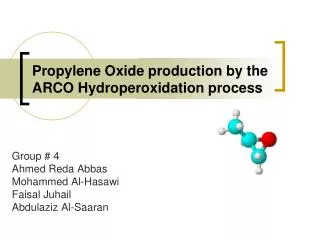
Kuwait University College of Engineering & Petroleum Depatment of Chemical Engineering. PROPYLEN OXIDE CO-PRODUCTION WITH t-BUTYL ALCOHOL BY THE TEXACO HYDROPEROXIDATION PROCESS. Designer: Sultan Alharbi Supervised by: Prof.M.Fahim ENG: Yousif Ismail. Outline :.

E N D
Kuwait University College of Engineering & Petroleum Depatment of Chemical Engineering PROPYLEN OXIDE CO-PRODUCTION WITH t-BUTYL ALCOHOL BY THE TEXACO HYDROPEROXIDATION PROCESS Designer: Sultan Alharbi Supervised by: Prof.M.Fahim ENG: Yousif Ismail
Outline : 1- Heat exchanger ( heater , cooler ) 2- Distillation column 3- Reactor 4- Pump design 5- Compressor
Heat Exchanger Design Objectives: For E-104: - To increase the temperature For E-103: - To decrease the temperature
Assumptions: - Use shell and tube heat exchanger. - Assume the refrigent inter in tube side in cooler and steam in heater The value of the overall heat transfer coefficient was assumed to be: - For (E-103) = 300 w/m^2C. - For (E-104) = 900 w/m^2C. - For E-103 refrigent inlet temperature (t1) = -10 C refrigent outlet temperature (t2) = 35 C -For E-104 Steam inlet temperature (t1) = 200 C Steam outlet temperature (t2) = 70 C
Main design procedures: Main design procedure: Calculate the duty or heat load. Where, m: mass flow rate, kg/hr Cp: specific heat, kJ/kg°C ∆T: temperature difference, °C Collect physical properties.
-Calculate Log mean Temperature Where, DTm = Ft DTlm. ∆Tlm : log mean temperature difference. T1 : inlet shell side fluid temperature. T2 : outlet shell side temperature fluid temperature. t1 : inlet tube side fluid temperature . t2 : outlet tube side fluid temperature. -Assume U : overall heat transfer coefficient, W/m2oC -Calculate heat transfer area required.
- Calculate area of one tube, m2. Where -Outer diameter (do), (mm) -Length of tube (L), (mm) - Calculate number of tubes = provisional area / area of one tube
- Calculate bundle diameter. Where - Outside diameter (mm). - Number of tubes. - K1 & n1 are constant.
- Calculate shell diameter. Ds = Db + Bundle diametrical clearance - Find tube side heat transfer coefficient hi, W/m2°C - Find shell side heat transfer coefficient ho, W/m2°C
Calculate U overall heat transfer coefficient using: Where : - Uo : overall coefficient based on outside area of the tube ,w/m^2.C - ho : outside fluid film coefficient, w/m^2.C, from Table (12.2) - hi : inside fluid film coefficient ,w/m^2, from Table (12.2) - hod : outside dirt coefficient (fouling factor) ,w/m^2.C - hid : inside dirt coefficient (fouling factor),w/m^2.C - kw : thermal conductivity of the wall material w/m.Cs for cupronickel - di : tube inside diameter m - do : tube outside diameter m
-Calculate tube and shell side pressure drop. - Calculate Shell thickness. Where - t: shell thickness (in). - P: internal pressure (psig). - ri: internal radius of shell (in). - EJ: efficiency of joints. - S: working stress (psi). - Cc: allowance for corrosion (in).
Distillation ColumnT-(102) design Objective : To separate TBHP from t-Butanol Assumptions 1. Tray column. 2. Sieve plate. 3. Material of the distillation is carbon steel. 4. Plate spacing= 0.6 m 5. Efficiency = 50% 6. Flooding % = 85% 7. Weir height = 50 mm 8. Hole diameter = 5 mm 9. Plate thickness =5 mm
Main design procedures: 1) Actual number of stages = (hysys number stages/η) 2) FLV= ( Lw / Vw)*( ρv / ρL)^.5 Where:- Lw: liquid flow rate ρL: liquid density Vw: vapor flow rate, ρv :vapor density FLv: liquid-vapor flow factor 3) Find K1 (Top) & K1 (Bottom) from fig. K1correction = (σ/0.02)^.2*K1 Where:- σ: Surface tension
4)Uf (bottom)= K1 ((ρL- ρv)/ ρv) 0.5 Uf (Top) = K2 ((ρL- ρv)/ ρv) 0.5 Where: Uf : flooding vapor velocity K1: constant obtained from figure 5) uv = uf * x Where:- Uv : maximum velocity X : percentage of flooding at max flow
6) Max flow-rate = (Lw*Mwt / ρL*3600) Where:- Max.: Maximum Volumetric Flow rate. Lw: liquid flow rate ρL: liquid density M.wt: molecular weight 7) Anet = Mmax/uv Where:- Anet: Net area required 8) Ad = An/(1-y*10^-2) Where: Ad: down comer area
9) D =(Ad*4/(3.14))^.5 Where:- D: column diameter 10) H= (Tray spacing * actual NO. stage ) + D Where:- H: Column height 11) MVL =(Lbottom*Mwt)/(3600* ρL) Where:- MVL: maximum volumetric liquid rate
12) Ac = (3.14/4)*D^2 Ad = 0.12Ac An = Ac-Ad Aa = Ac-2Ad Ah take %10 Aa as first trial = %10*Aa Where: - Ac: column area Aa: active area Ah: hole area Ad= Downcomer area
13)max Lw = Lw*Mwt/3600 min Lw @ % turn down = %*max Lw max how =750 (max Lw/ρL*wierlength)^(2/3) min how =750 (min Lw/ ρL*wierlength)^(2/3) actual minimum vapor = vapor rate min/Ah Where:- max Lw: maximum liquid rate. min Lw : minimum liquid rate.
14) The actual min vapor velocity = vapor rate min/An 15) uh = Vw max/Ah hr = 12.5E+03/ ρL Where:- uh: maximum vapor velocity through holes max.Vw: maximum volumetric flow rate hd: dry plate drop hr: Residual head
Aap= wier length*hap • hdc= 166*(max liquid flowrate/ ρL*Aap)^2 • hb= Minimum rate (hw + how) + ht + hdc • Where:- • Aap: Area under arpon • hdc: head losses in the down comer • tr= • Where : • tr : residence time , should be > 3 s
18) Percent flooding = Where :- uv: vapor velocity, uf: flooding vapor velocity 19) Number of holes Area of one hole = (π/4)*(hole diameter^2) Total number of holes = Ah / area of one hole Holes on one plate = total Number of holes/number of stages
20) Area of condenser& reboiler = Q/(U*∆T) 21) Thickness = [(ri P)/(Ej S-0.6P)]+Cc Where:- ri = Inside radius of the shell P =Maximum allowable internal pressure S = Maximum allowable working stress EJ = Efficiency of joints Cc = Allowance for corrosion
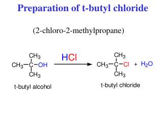
Reactor Design Objectives: - R-101: To produce TBHP from Isobutane and oxygen. (CH3) 3 CH + O2 → (CH3)3COOH
Assumptions: -The limiting reactant is (CH3) 3CH in the R-101 reactor . -The conversion equal to 0.24 in the R-101 reactor
Main design procedures: 1.Find Volume: V=(Fao-Fa)/-ra = (Fao-Fa)/kCao(1-X) Where Fao : inlet mass flow Fa : outlt mass flow K : kinetic rate Cao : density*Fao/total mass flow rate X : conversion
2. Find diameter of reactor Volume = PI * (D/2)^2 * H = PI * D^3 Where H = 4D D = (V/PI)^1/3 3. Calculate the height of reactor: Height of reactor (H) = 4 * Diameter Total height of reactor = 0.5 + 0.5 + H+ 2 (D/2)
4. Calculate the thickness Where, t is thickness in inch P is internal pressure in psig, ri is the radius of the reactor, in, S is the stress value of carbon steel (S=13700 psia), Ej is the joint efficiency (Ej=0.85 for spot examined welding), Cc is the corrosion allowance (Cc=1/8 in) 6. Calculate cost from www.matche.com
Compressor Design Objectives: -To increase gases pressure.
Main design procedures: • 1.Calculate the compression factor (n) using the following equation: Where, P1,2 : is the pressure of inlet and outlet respectively (psia) T1,2 : is the temperature of the inlet and outlet respectively (R)
2. Calculate the work done in Btu/lbmol by: Where, R is the ratio of the specific heat capacities (Cp/Cv) 3. Calculate the horse power, Hp using the following equation: Hp=W*M Where, M is the molar flow rate in lbmol/s 4. Calculate the efficiency of the compressor using the following equation:
Where , Mw :is the molecular weight of the gas in the stream CP :is the specific heat capacity (Btu/lb◦ F ) 5. Calculate the cost of the compressor from www. Matche . com
Pump Design • Assumptions: • Centrifugal pump. • Design procedures: • 1.Calculate the flow rate • m= ρ *Q • 2.Calculate the work shift • Ws = -ha * g • 3.Assume efficiency ζ.
4.Calculate the Brake horse power • = (-Ws * m) / (ζ * 1000) • 5.Calculate the diameter, d. • Where, • ∆P is the pressure difference between the inlet and outlet streams in kpa • Q: flow rate kg/s • ρ: the density of the fluid kg/m3 • μ: viscosity cp • D: pipe diameter mm 6. Calculate the cost of the compressor from www. Matche . com