Download
1 / 12
140 likes | 333 Vues
Analogue Input/Output. Many sensors/transducers produce voltages representing physical data. To process transducer data in a computer requires conversion to digital form. Examples:- reading temperature from a thermocouple processing speech from a microphone

E N D
Analogue Input/Output • Many sensors/transducers produce voltages representing physical data. • To process transducer data in a computer requires conversion to digital form. Examples:- • reading temperature from a thermocouple • processing speech from a microphone • Many output devices require variable control, not just two digital logic levels • To control these devices from a computer requires conversion from digital to analogue form.
Analogue Output • Digital to Analogue Converter (DAC) • DAC Characteristics • resolution = 1/2n where n is the number of bits – step size • Max. digital output = 2n – 1 • output voltage range – determined by reference voltage (Vref and AGND) • Step size in volts = resolution x voltage range • Max output voltage = (2n – 1)/ 2n x voltage range • uni-polar / bipolar types • slew rate – rate of change of output. • interface – parallel (fast) or serial (slower but uses fewer connections)
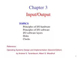
d1 d3 d2 d0 DAC principles – Example 4-bit DAC • Sum currents with operational amplifier R 2R Vref/2 1 Vo = - Vref(Rf/Rinput) 4R Vref/4 0 - Vo 8R Vref/8 + Vo = -Vref(digital value/2n) 1 Example: with 4-bit value = 1011 Vo = -Vref(d3/2 + d2/4 + d1/8 + d0/16) Vo = -Vref(1/2 + 1/8 + 1/16) Vo = -Vref(11/16) 16R Vref/16 1 Vref AGND
Digital to Analogue conversion • Previous design needs many different precise resistor values • Resisters need to have a tolerance less than the resolution. E.g. 8-bit resolution = 1:28 = 1/256 = 0.00390625resolution = 0.390625% • Alternative is R-2R ladder arrangement • R-2R ladder - only requires 2 different resistor values.
Analogue Input • Main types (methods) of ADC • Successive approximation – good all-rounder • Flash – fastest type • Sigma-delta – good for audio • Dual slope integrating – slow but high resolution with good noise immunity • others – Sampling, ramp, charge balancing • Characteristics • resolution • conversion method • conversion time • input voltage range • interface – parallel (fast) or serial(fewer connections)
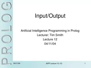
Conversion Control Interrupt request Busy Mut iplexer Result Register Start conversion AN0 Sample & Hold AN1 Converter VAREF VAGND ANn Typical ADC Block diagram Reference voltage
ADC – principle of operation • The voltage is presented to the ADC input. • The ADC is sent a signal to start conversion • While the conversion takes place the input voltage should remain stable. • The ADC outputs a signal to indicate that it is busy doing the conversion and should not be disturbed. • When the conversion is completed the ADC makes the result available and outputs a signal to indicate that the conversion has completed (e.g remove the busy signal)
Multiplexer • To convert several analogue inputs • use an ADC for each input or … • use one ADC and switch the inputs through a multiplexer • requires selection of input before each conversion is started • short delay required before conversion started to allow switching to occur and signal to settle.
Sample and Hold Circuit • Sample and Hold (S&H) • while conversion takes place voltage must remain stable • sample voltage – input connected to S&H • voltage held on a capacitor • sample time – charging time of capacitor • input signal disconnected from S&H
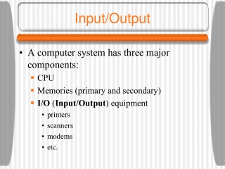
ADC Control Registers The ADC is configured and controlled through two Special File Registers, ADCON0 and ADCON1. Additionally the PIR1 contains the ADIF bit (Analogue to Digital Interrupt Flag) which is set when a conversion is complete. ADCON0 ADCON1
ADC Result Format • The 10-bit result can be placed in ADRESH and ADRESL in one of two ways depending on the ADFM bit in ADCON0 • With left justified an equivalent 8-bit ADC can be obtained by simply using ADRESH and ignoring ADRESL.