Download
1 / 19
340 likes | 1.17k Vues
Outline. Whole-cell vs Cell-attached patch Current Clamp Components of an action potential Voltage Clamp Conductances of an action potential Channel Structure Single channel recordings. Cell-attached Patch. Whole-cell Patch. G Ohm Seal between pipet and membrane.

E N D
Outline Whole-cell vs Cell-attached patch Current Clamp Components of an action potential Voltage Clamp Conductances of an action potential Channel Structure Single channel recordings
Cell-attached Patch Whole-cell Patch GOhm Seal between pipet and membrane Pipet and cell are contiguous Record single channels Monitor spiking Measure “macro” currents Synaptic events
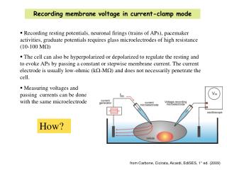
Current Clamp Done in whole-cell configuration Monitors the potential of the cell- therefore units will be in volts By convention V= Einside – Eoutside Upward deflections are depolarizing; downward are hyperpolarizing -55 mV
Current Clamp Done in whole-cell configuration Monitors the potential of the cell- therefore units will be in volts By convention V= Einside – Eoutside Upward deflections are depolarizing; downward are hyperpolarizing -55 mV
Current Clamp Done in whole-cell configuration Monitors the potential of the cell- therefore units will be in volts By convention V= Einside – Eoutside Upward deflections are depolarizing; downward are hyperpolarizing -55 mV Membrane time constant = RmC
Current Clamp Done in whole-cell configuration Monitors the potential of the cell- therefore units will be in volts By convention V= Einside – Eoutside Upward deflections are depolarizing; downward are hyperpolarizing -55 mV
Current Clamp Done in whole-cell configuration Monitors the potential of the cell- therefore units will be in volts By convention V= Einside – Eoutside Upward deflections are depolarizing; downward are hyperpolarizing -55 mV Slope = I/Vm = g (conductance) 1/g = Rm
Current Clamp Done in whole-cell configuration Monitors the potential of the cell- therefore units will be in volts By convention V= Einside – Eoutside Upward deflections are depolarizing; downward are hyperpolarizing -55 mV Activation of Ih
Current Clamp Done in whole-cell configuration Monitors the potential of the cell- therefore units will be in volts By convention V= Einside – Eoutside Upward deflections are depolarizing; downward are hyperpolarizing
Action Potentials The Hodgkin-Huxley Model The squid giant axon action potential had only sodium and potassium currents…. Other cells’ action potentials are shaped by a number of other conductances.
Beyond Hodgkin-Huxley Action Potentials Storm, 1987
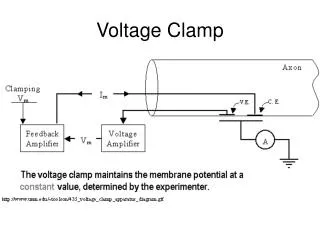
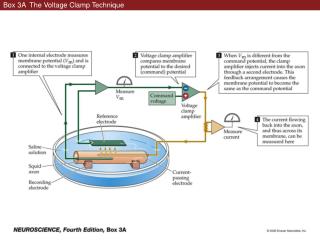
Voltage Clamp Used to measure currents that underlie changes in potential ITotal = IIonic + IC where IC = C(dV/dt) Thus, by clamping the cell at a certain voltage, dV/dt=0 and IT = II Measures the amount of current needed to hold the cell at a given potential- therefore units will be in amps Downward (negative deflections) are inward currents; upward are outward L-Type Calcium Channel
Voltage Clamp Series resistance is due to the resistance of the extracellular solution (Ohms) and the access through the pipet tip (MOhms). Voltage Clamp errors: 1. Current across Rs causes a voltage drop. 2. R in series with C forms a low-pass filter.
Hodgkin and Huxley, 1952 Different conventions: 1. Vrest= 0 mV not -60 mV 2. Negative potentials are depolarizing 3. Inward currents are positive
Hodgkin and Huxley, 1952 TAIL CURRENTS allow you to isolate voltage and time dependent properties of a channel from the driving force on the ion. Activation Inactivation Recovery from inactivation Deactivation
Increased Input R Can locally apply drugs extracellularly Can expose intracellular domain of channel to variable solutions
Things to look for… Ion concentrations in internal and external solutions Temperature