Chapter 15: Networks
Learn about LANs and WANs, including Ethernet and Token Ring configurations, circuit switching, and the challenges with circuit-switched networks.

Chapter 15: Networks
E N D
Presentation Transcript
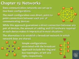
Chapter 15: Networks Data communication networks are set up in two basic configurations. The meshconfiguration uses direct, point-to-point connections between each pair of communicating devices. While this approach guarantees a direct connection between any pair of devices, the amount of cabling and I/O hardware required at each device makes it impractical in most situations. The alternative is to establish a broadcast network in which network lines are shared. Simple configurations associated with the broadcast approach include the ring and bus topologies, at left and right, respectively. Chapter 15 Networks Page 162
Local Area Networks Bus Cable Computer Computer Computer Computer Computer Computer LANs are privately owned networks containing perhaps dozens of devices. Example: Ethernet Ethernet uses a bus configuration and a protocol for accessing the bus called CSMA/CD. • CS - Carrier Sense: Each machine constantly listens to the traffic that’s passing by on the bus. • MA - Multiple Access: Every machine has equal access to the communication medium (i.e., the bus). • CD - Collision Detection: Each machine is capable of detecting whether its transmitted message “collided” with that of another machine, thus corrupting the message and forcing a retransmission. Chapter 15 Networks Page 163
Ethernet Carrier Sense: Incoming Traffic Bus Cable Computer Computer Computer Computer Computer Computer As messages pass by, each machine examines the first few bits of the message, the “address” of the message, and determines whether or not the message is intended for itself. message message message When the destination machine sees its address in the message’s prefix, it copies the passing message as the original proceeds down the bus. Chapter 15 Networks Page 164
Ethernet Carrier Sense: Outgoing Traffic Bus Cable Computer Computer Computer Computer Computer Computer When a machine wants to transmit a message, it waits a system-dependent amount of time, using its carrier sense to see if any traffic appears on the bus. If not, it transmits its message and “hopes” that no collision occurs. message When the transmitting machine detects no passing traffic for a certain time interval, it places its message on the bus. Chapter 15 Networks Page 165
Ethernet Carrier Sense: Colliding Traffic Bus Cable Computer Computer Computer Computer Computer Computer After a machine transmits a message, it continues to use its carrier sense to see if there’s any difference between its transmitted message and the message on the bus. If so, it interprets the problem as a collision. message message When each transmitting machine detects that its message has been corrupted, it waits a random interval of time, and then retransmits. Chapter 15 Networks Page 166
A LAN Alternative: Token Ring Ring Computer Computer Computer Computer Computer Computer Computer Computer Computer Computer Computer Computer Computer Collisions tend to exacerbate traffic problems on congested Ethernet LANs, so an alternative to the CSMA/CD approach is desirable. message TOKEN TOKEN message message Token Ring uses a ring topology, with a specially formatted “token” message perpetually traversing the ring. When a machine wishes to transmit, it merely waits for the token to arrive, removes it, and transmits its message. When its message returns to the transmitting machine, it’s removed from the ring, and the machine places the token back on the ring. Chapter 15 Networks Page 167
Wide Area Networks WANs are large collections of smaller networks, with special interconnection devices known as “routers” to make adjacent sub-networks compatible. Router Router Router Router Router Router Chapter 15 Networks Page 168
Switching Data communications is characterized by two switching technologies. Technology #1: Circuit Switching Once the circuit is established, it is maintained until one of the endstations terminates the connection. Chapter 15 Networks Page 169
Problems with Circuit Switching Circuit switching has one great advantage: once established, the circuit is dedicated, i.e., a communication line is completely open until formally terminated. However, this approach has a number of serious problems: • Many networked applications don’t require a dedicated circuit, so reserving a communication line until an endstation formally terminates it can represent a serious waste of resources. • The route originally selected for the circuit may be optimal to begin with, but may prove to be suboptimal as the communication continues. • An entire, end-to-end path must be found and reserved before any communication is allowed between the two endstations; this is definitely not conducive to many modern applications (e.g., Web surfing, videoconferencing). • Transmission errors are propagated all the way to the destination, requiring retransmission across the entire network. Chapter 15 Networks Page 170
An Alternative to Circuit Switching Technology #2: Packet Switching The source’s message is broken into manageable “packets” that are transmitted to the destination individually, not necessarily along the same path. Chapter 15 Networks Page 171
The Pros and Cons of Packet Switching • Packet switching remedies circuit switching’s principal problems: • Lines aren’t dedicated, so their utilization is higher. • Messages are “packetized”, so line-sharing is reasonably fair. • Routing may be dynamic, i.e., an alternate route may be chosen when traffic patterns change. • The entire route does not have to be chosen prior to sending any data. • Errors aren’t propagated end-to-end. • However, packet switching does have its own set of problems: • Switches must be programmed to make sophisticated routing decisions. • Switches must manage memory for queued packets that await forwarding. • Packets must be prefixed with control headers, increasing overhead. • Endstations must deal with missing packets and out-of-order packets. • Without a dedicated circuit, transmission times become unpredictable. Chapter 15 Networks Page 172
Multiplexing To more efficiently utilize a physical medium, multiple higher-level connections might “share” the medium simultaneously. Frequency-Division Multiplexing The spectrum of frequencies transmittable via the physical medium is divided into several channels (e.g., cable TV). Time-Division Multiplexing Each transmitter is allocated a periodic time interval in which to transmit. Chapter 15 Networks Page 173
Code Division Multiplexing Time Division Multiplexing Everyone gets to talk using the entire bandwidth, but they have to take turns talking. (Commonly user with fiber optics) Frequency Division Multiplexing Everyone gets to talk at the same time, but only across their narrow channels. (Commonly used with copper cables) Code Division Multiplexing Everyone gets to talk simultaneously, using the entire bandwidth! They do this by coding their transmissions in a unique fashion (as if every pair were speaking a different language, and each other language merely sounds like background noise). (Commonly used with wireless communications) Chapter 15 Networks Page 174
Modems Digital data must be modulated into analog signals if it’s going to be transmitted across an analog medium. After transmission, it must be demodulated back into its original digital form. Dial-in pool of 96 modems: Six terminal servers, each connecting 16 modems to a LAN Cables between the workstation and the modem and between the modem and the telephone jack Chapter 15 Networks Page 175
cos(ct) m1(t) X cos(ct) m1(t) + sin(ct) m2(t) X m2(t) sin(ct) 2cos(ct) m1(t) m1(t)+cos(2ct) m1(t) +sin(2ct) m2(t) FILTER OUT THE HIGH FREQUENCIES X cos(ct) m1(t) + sin(ct) m2(t) m2(t)+cos(2ct) m2(t) +sin(2ct) m1(t) X m2(t) 2sin(ct) Modulation and Demodulation Modulation of the digital signals m1 and m2 is effected at left via products with trig functions. Upon arrival, the message is demodulated below via trig multiplications, trig identities, and high-frequency filtering. Chapter 15 Networks Page 176
Modem Interfaces • The EIA-232D connector connects a modem to a computer. • It uses a 25-pin connector, with each pin having a different meaning. • The meaning of each pin is activated by applying a voltage across it. For example... Pin 20: Data Terminal Ready (i.e., “Hey! The computer’s ready to send something to the modem!”) Chapter 15 Networks Page 177
Network Protocol Layers Layer 5 Layer 5 Layer 4 Layer 4 Layer 4 Layer 4 Layer 3 Layer 3 Layer 3 Layer 3 Layer 2 Layer 2 Layer 2 Layer 2 Layer 2 Layer 1 Layer 1 Layer 1 Layer 1 Layer 1 Source Host Intermediate Router Low-Level Bridge Intermediate Router Destination Host In an effort to simplify networks, they are often organized as layered hierarchies of protocols, with hardware-intensive protocols on the bottom and user applications at the top. Physical Medium Chapter 15 Networks Page 178
Communicating Via Layered Protocols Layer 5 message Layer 4 Layer 4 hdr4 message hdr4 message Layer 3 Layer 3 hdr3 hdr4 msgA hdr3 hdr4 msgB hdr3 hdr4 msgB hdr3 hdr4 msgA Layer 2 Layer 2 hdr2 hdr3 hdr4 msgA trl2 hdr2 hdr3 hdr4 msgB trl2 hdr2 hdr3 hdr4 msgB trl2 hdr2 hdr3 hdr4 msgA trl2 Layer 1 Layer 1 hdr1 hdr2 hdr3 hdr4 msgB trl2 hdr1 hdr2 hdr3 hdr4 msgA trl2 Consecutive network nodes only communicate directly at the lowest (hardware) layer; to communicate at higher layers, networking software inserts certain relevant data as headers and trailers to the message coming from the source. Chapter 15 Networks Page 179
Layered Protocol Models Several models have been developed to implement protocol hierarchies for networks. Reference Model #1: Open Systems Interconnection (OSI) Chapter 15 Networks Page 180
Reference Model #2: Transmission Control Protocol/Internet Protocol (TCP/IP) Chapter 15 Networks Page 181
The IP Protocol The Internet Protocol was designed for three primary purposes: 1. Define the data format to be used by messages travelling through TCP/IP networks. 2. Route the data through the Internet by selecting appropriate paths. 3. Process packets, generate error messages, and discard packets in such a way to ensure “unreliable” packet delivery. Chapter 15 Networks Page 182
The IP Header Version HdrLen Service Type Total Length Identification Flags Fragment Offset Time To Live Protocol Header Checksum Source IP Address Destination IP Address Options & Padding (if any) Version HdrLen Service Type Total Length Identification Flags Fragment Offset Time To Live Protocol Header Checksum Source IP Address Destination IP Address Options & Padding (if any) Version: The version of IP used to create the packet, used by nodes to process it correctly. HdrLen: The length of the header in 32-bit words (because the Options field has no fixed size). Service Type: Six bits to represent the relative priority and delay sensitivity of the packet. Total Length: The length of the entire packet in bytes (16-bit field means a 65,535-byte max). Identification: All fragments of the same packet have the same ID number. Flags: Don’t-Fragment flag and More-Fragments flag. Fragment Offset: Offset from start of packet (in bytes) of current fragment. Time To Live: Length of time (in seconds) the packet may stay in the Internet. Protocol: Global ID # of the protocol used to create the packet (e.g., TCP). Header Checksum: Error-checking sum of all of the 16-bit values in the header. Source IP Address: 32-bit IP address of the packet’s original source. Chapter 15 Networks Page 183 Destination IP Address: 32-bit IP address of the packet’s final destination. Options & Padding: Options include: No-operation-just-align; Military-security-application; Loose-source-routing; Record-route; Strict-source-routing; Record-internet-timestamps.
IP Addresses There are three principal classes of IP addresses, with all endstations on the same network given a common prefix: CLASS A - for networks with at least 216(65536+) endstations: Host ID 0 Network ID CLASS B -for networks with between 28 and 216(256-65535) endstations: 10 Network ID Host ID CLASS C - for networks with less than 28(0-255) endstations: 110 Network ID Host ID Chapter 15 Networks Page 184
The Domain Name System(DNS) A hierarchical system of domains and subdomains has been established to permit stations to communicate with other stations by “name”. A station contacts its server, who knows the location of the required domain server, who knows the location of the required subdomain server, etc., until the required endstation is located, whereupon its IP address is returned. Chapter 15 Networks Page 185
Electronic Mail User Interface Outgoing Mail Spool Area Client (Background Transfer) TCP Connection for Outgoing Mail User Sends Mail Mailboxes for Incoming Mail Server (To Accept Mail) TCP Connection for Incoming Mail User Reads Mail Alias Database User Interface Outgoing Mail Spool Area Client (Background Transfer) TCP Connection for Outgoing Mail User Sends Mail Alias Expansion & Forwarding Server (To Accept Mail) TCP Connection for Incoming Mail User Reads Mail Mailboxes for Incoming Mail The background transfer process sweeps through the spool area periodically (typically, twice an hour). Whenever it finds an undelivered message or whenever a user deposits new outgoing mail, the background process attempts delivery. Rather than resorting to the Domain Name System for each outgoing message, and to accommodate locally used aliases for incoming messages, most systems provide mail forwarding software with a mail alias expansion mechanism. Chapter 15 Networks Page 186
Client System Server System control process control process Operating System Operating System TCP/IP Internet Client System Server System data transfer control process control process data transfer Operating System Operating System TCP/IP Internet File Transfer Protocol (FTP) One active TCP connection before and after data transfer, just for control. Two active TCP connections during data transfer, one for control and one for data. Chapter 15 Networks Page 187
Firewalls Firewall! To ensure the security of a private network, “firewall” programs have been developed. A common approach is to filter incoming and outgoing packets based upon header information, and to use an application gateway to inhibit application-specific traffic. My Secure Network packet packet packet packet packet Incoming packets for bad address/port combinations are rejected (e.g., no outsider can “finger” an internal site). Incoming or outgoing packets are rejected on the basis of size or payload info. Outgoing packets for bad address/port combinations are rejected (e.g., no insider can “http” an external site). Chapter 15 Networks Page 188