Microscopy: Overview of Different Methods
590 likes | 610 Vues
Microscopy: Overview of Different Methods. EML 5930 (27-750) Advanced Characterization and Microstructural Analysis A. D. Rollett, P.N Kalu Spring 2008. (MACRO)TEXTURE. Review : Recall that X-ray texture (macrotexture):

Microscopy: Overview of Different Methods
E N D
Presentation Transcript
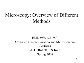
Microscopy: Overview of Different Methods EML 5930 (27-750) Advanced Characterization and Microstructural Analysis A. D. Rollett, P.N Kalu Spring 2008
(MACRO)TEXTURE Review: Recall that X-ray texture (macrotexture): • Provides an overview of the crystallographic texture of material - only texture information is obtained. • Provides the volume fraction of the specimen, which has a particular orientation. • Does not tell how grains are distributed in the material.
Lack of a direct connection between the study of texture and microstructure. • Parallel but separate investigations are needed in order to obtain microstructural data.
MICROTEXTURE • Microtexture technique provides concurrently the spatial location and the orientation of individual grains in a sample. • This technique can be referred to as the modern approach to texture investigation. • Until recently, the orientation of individual crystals can only be determined by Selected Area Diffraction Pattern (SADP) technique on TEM - very tedious.
Phenomena that can be investigated using microtexture: • Effect of property variation as a function of orientation • Misorientation between neighboring grains or distribution of grain boundary geometry, which can result in the grain boundary/property relationship. • Correlations between geometrical and orientational parameters of the grains • Orientation variations within individual grains • Phase Identification/Relationships • Direct ODF measurement
Macrotexture or Microtexture analyses techniques rely on the diffraction of radiation by a crystal lattice. • The exploring radiation can be used as an experimental tool for microtexture measurement only if the probe size is smaller than the microstructural unit.
Diffraction: • Crystal structure analysis is usually based on diffractionphenomena caused by the interaction of matter with X-rays, electrons, or neutrons. • Therefore, when either X-rays or electrons interact with crystalline material, they are: (a) Subject to diffraction – have similar wave properties. (b) Monochromatic radiation - produce a series of strongly diffracted beams leaving the crystal in defined and predicted directions.
The resultant diffraction pattern is given by Braggs Law, and this is given by …….. 1 where, d: Interplanar spacing : Grazing angle of incidence (Bragg angle) n: Integer (0, 1, 2, 3 ….. ) : Wavelength of the incident electrons • Note • With diffraction, we use Reciprocal lattice in which sets of lattice planes are represented simply by a set of points in reciprocal space.
The Reciprocal Lattice • Very useful in metric calculations • Let a, b, c be the elementary translations of a space lattice (direct lattice) • A second lattice, reciprocal to the first one, is defined by translations a*, b*, c*, which satisfy the following conditions: a*. b = a*. c = b*. a = b*. c = c*. a = c*. b = 0 and a*. a = b*. b = c*. c = 1 • Equation 2a suggests that a*is normal to the plane (b,c), b*is normal to the plane (a,c), and c*is normal to the plane (a,b), (2a) (2b)
The magnitude and sense of a*, b*, c*are fixed by (2b) • According to (2a), a* may be written as: a* = p (b ^ c) where p is a constant. The value of p is obtained by if the scalar product of both sides of (3a) by a is taken: a* . a = 1 = p (b ^ c . a) = pV • Therefore, p = 1/V, and equation (3a) can be written as: a* = { (b ^ c)}1/V ……… (3a) (3b)
Table 1. The Characteristics of Light and Various Radiations Used for Texture Measurement by Diffraction. • Electrons are the only radiation in which their penetration depth and interaction volume is small enough to allow diffraction from individual grains (very small volume). • Therefore, only electrons can be used for MICROTEXTURE
Microtexture technique can either be TEM-based or SEM-based. • Until mid-1980, the TEM-based was the major microtexture technique, although an SEM-based Selected Area Channeling technique was available. • Modern SEM-based technique known as can now be classified into two: • manual • automated
MICROSCOPY Introduction: • Several new microscopy-based microcharacterization techniques have been developed over the last four decades, which have significantly extended the ability to study the microstructure of materials. • In addition to Optical Metallography, there is a range of Electron Optical techniques. • Electron microscope (developed in 1931) was initially used for the study of biological systems, but thin foil techniques in the mid-1950’s enabled microstructural investigations to be undertaken on metals and alloys.
Typical Information from Electron Microscope: • Chemical composition of materials can be obtained using electron microprobes to produce characteristic X-ray emissions and electron energy losses. • Imaging (surface) can be characterized using secondary electrons, backscattered electrons, photo-electron, Auger electrons and ion scattering. • Crystallography or crystal structure information can be obtained from backscattered electrons (diffraction of photons or electrons). The various studies of materials exploit at least one of the above information, as well as the excellent spatial resolution of electron microscopes.
Figure 1. Summary of the various signals obtained by interaction of electrons with matter in an electron microscope
Comparison between Optical and Electron Microscopy: • In many ways, electron microscopes (Scanning and Transmission) are analogous to light microscopes. • Fundamentally and functionally, electron microscopes (EM) and optical microscopes (OM) are identical. • That is, both types of microscopes serve to magnify minute objects normally invisible to the naked eyes. • Basically, component terminology of an EM is similar to that of an OM. Both microscopes consist the following (see Figures 2 and 3):
Figure 2. A simple optical, transmission microscope system comprising a condenser and objective lens.
(a) Source of Illumination as light source • Electron Gun produces an electron beam by thermionic or field emission - EM • Lamp produces light beam (including uv rays) - OM (b) Condenser Lens system projects a near parallel radiation on to the specimen • Electro-magnets of variable focal length are the lenses in EM. • Curved transparent substance - OM (c) Series of Imaging Lenses form the Image of the specimen
Although (a) to (c) above address the basic differences between the two types of microscopes, a detailed comparison is provided in Table 1.
ELECTRON EMISSION • The liberation of electrons from the surface of a solid into vacuum. • The process of electron emission is similar to that of ionization of a free atom • The energy of the electrons in an atom is lower than that of an electron at rest in vacuum; consequently, in order to ionize an atom, energy must be supplied to the electrons in some way or other. • A solid can only emit electrons if some of the electrons have energies equal to, or larger than, that of an electron at rest in vacuum. This may be achieved by various means, such as by • heating, irradiation with light (photoemission), • bombardment with charged particles (secondary emission), or • using of a strong electric field (field, or cold, emission).
ELECTRON SOURCES • Electron sources in electron beam instruments are required to provide either • a large total current beam of about 50 m diameter - low magnification TEM, or • a high intensity probe of electrons as small as 0.5 nm in diameter - SEM • There are three different types of electron source available
a) Thermionic tungsten hairpin filament This is usually heated to about 2800 K by direct resistance heating. The surrounding grid, known as the Wehnelt cylinder, and the anode, which is at earth potential, act as an electrostatic lens. For an operating condition of 100 kV, the brightness is about 3 x 10⁵ A cm-2 sr-1.
(b) Figure 4. Schematic diagram of a conventional tungsten thermionic source. (a) the filament F and Wehnelt cylinder (b) schematic ray path showing focusing action.
b) Lanthanum hexaboride crystal (LaB6) The only difference between the conventional assembly illustrated in Figure 4 and a modern LaB6 assembly is that extra pumping holes are present in the Wehnelt cap to ensure a better pumping speed near the tip. Higher current (greater than the tungsten) is obtainable in small probes. The brightness of a LaB6 can be as high as 107 A cm-2 sr-1 at 100kV.
c) Field emission source • The emission of electrons from a metal or semiconductor into vacuum under the influence of a strong electric field. • Field emission - electrons tunnel through a potential barrier, rather than escaping over it as in thermonic emission. • The effect is purely quantum-mechanical, with no classical analog.
In most cases, it is a <111> orientation crystal of tungsten, and a Wehnelt cylinder, which is raised to an extraction potential up to about 4 kV in order to cause emission from the tip of the crystal. • There is a requirement of high vacuum for this source • The brightness of cold or thermal emission source can be about 104 times of a conventional tungsten filament. • The high brightness of this source make them preferable for scanning instruments. • Cold, thermal or Schottky
Schotty Field Emission Source Electron Gun for SEM • Source: • Schotty field emitter (ZrO/W • High brightness • Highly-stable electron beam • High current density • 100 nm spot size at 5 nA sample current • The field emission source – current density can be maximize and still produce a 100 nm spot size at 5 nA. • Optimised for Auger analysis at very high spatial resolution with SEM.
Electron lenses in microscopes are generally electromagnetic. • There are three types of magnetic lenses in uses (refer to Figure 5): (a) a multi-layer coil; i.e., an air-core solenoid coil (b) a coil enclosed by soft iron plates (in order to reduce leakage flux) containing a gap (in order to concentrate the induction field) and (c) a coil enclosed by soft iron plates containing a gap and internal soft iron pole pieces (in order to ensure a high intensity magnetic field)
Almost all modern electron microscopes use pole pieces for high resolving power and high magnification. • The function of such an electron lens is more or less the same as that of horse-shoe magnets symmetrically arranged about an axis. • Accordingly, all the parallel electron beams incident to the curved magnetic field converge at one point.
ELECTRON OPTICS • The action of a magnetic field on an electron is described by a well-known right hand rule where thumb, first and second finger are used to represent the terms in a vector product • The force F which an electron of charge -e experiences when travelling with velocity v, due to a magnetic field B, is given by: …………(4a)
Figure 6. Schematic diagram of the action of a cylindrical magnetic lens on the path of non-axial electrons.
and the magnitude of the force is then given by …………..(4b) where is the angle between B and v. If the initial velocity of an electron is divided into two components, vp parallel to B and vo perpendicular to B, then the value of vp will be unchanged by B (since will be zero) and the force resulting from B and vo will result in a circular motion of the electron about B (see Figures 7 and 8).
Figs. 7 & 8 shows the trajectory of an electron passing through such a magnetic field. • Although the electron beam path in a magnetic lens is not the same as the light ray path in an optical lens, the results are similar. • As shown in Figs. 7 & 8, the electron travels rectilinearly, crosses the axis, moves through the magnetic field along a spiral orbit, approaches the axis, crosses the axis again, and travels rectilinearly.
Figure 8. Schematic diagram showing the trajectory of an electron through a magnetic lens.
The radius r of this spiral motion is given by: ……….(4c) Since generally, in electron microscopes, electron beams near the axis are used for forming an image, a is extremely small. This effect is similar to the converging action of an optical convex lens, and if the revolution of the electron about the axis is omitted, the converging action of an electron lens can be considered to be identical to that of an optical lens.
A magnetic lens containing pole pieces magnetized to near-saturation for concentrating magnetic flux in a very narrow space constitutes a thin lens. • The focal length f and rotation angle q are given as follows: …….. 5 where, V => Accelerating voltage = specific charge of electron e/m
RESOLUTION OF LENS • Resolution defines the smallest separation of two points in the object, which may be distinctly reproduced in the image. Light Microscope: The resolving power for light microscope is determined by diffraction aberration and can be defined as 1,2 ……….. 6 • where is the wavelength of the illumination, n is the refractive index of the medium in front of the lens, is the semi-angle (aperture angle) subtended by the object at the lens NA = n sinα= numerical aperture = measure of light-gathering ability = 0.95 (max. with air). Higher (~1.515) for oil-immersion objtvs. k is a constant usually taken to be 0.61.
Optical Microscope – = 50 nm (for white light Illumination) n sin = 0.135 (when fitted with an oil immersion lens) Therefore, it is possible to achieve a resolution of about 250 nm in Optical Microscopes. • Filters can also be used to enhance the resolving power of an objective. For light: • The shorter wavelengths are at the violet-blue-green end of the spectrum • The higher wavelengths are at the orange-red of the spectrum.
Electron Microscope – • De Broglie relationship relates the wavelength of electrons, , to their momentum, mv (m is the mass and v is velocity), by h – Planck’s constant, such that: ……… 7 • Since electrons are accelerated by a potential difference of V volts and have a kinetic energy K, where K is given as – ……... 8 Therefore, ……… 9
By considering equations (7) and (9), we have – ……. 10 The energy term eV is expressed in electron volts and represents that energy required to pass an electron through a potential difference of one volt ( 1 eV = 1.602 x 10⁻¹⁹ J).
When the velocity of the electron approaches the speed of light, v c, a relativistic correction is required for the voltage, such that ………………….. 11 where mo is the mass of the electron at rest. It is important to use this correction for cases when V 105 volts. Table 2 presents a chart of electron wavelength in relation to applied voltage.
Table 2.Variation of Electron Wavelength with applied voltage