Allowed and Forbidden Transitions
470 likes | 2.39k Vues
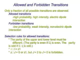
Allowed and Forbidden Transitions. Only a fraction of all possible transitions are observed. Allowed transitions -high probability, high intensity, electric dipole interaction Forbidden transitions -low probability, weak intensity, non-electric dipole interaction

Allowed and Forbidden Transitions
E N D
Presentation Transcript
Allowed and Forbidden Transitions Only a fraction of all possible transitions are observed. Allowed transitions -high probability, high intensity, electric dipole interaction Forbidden transitions -low probability, weak intensity, non-electric dipole interaction Selection rules for allowed transitions: * The parity of the upper and lower level must be different. (The parity is even if Sli is even. The parity is odd if Sli is odd.) * Dl = ±1 * DJ = 0 or ±1, but J = 0 to J = 0 is forbidden.
Additional Splitting Effects • Hyperfine splitting due to magnetic coupling of spin and orbital motion of electrons with the nuclear spin. • Isotope shift. Sufficient to determine isotope ratios. • Splitting in an electric field (Stark effect): Relevant for arc and spark techniques. • Splitting in a magnetic field (Zeeman effect): • * In absence of a magnetic field, states that differ only by their MJ values are degenerate, i.e., they have equivalent energies. • * In presence of a magnetic field, this is not true anymore. • * Can be used for background correction.
Pretsch/Buhlmann/Affolter/Badertscher, Structure Determination of Organic Compounds
Pretsch/Buhlmann/Affolter/Badertscher, Structure Determination of Organic Compounds
Stark Splitting For H: split a E For others: split a (E)2 www.wikipedia.org
Zeeman Splitting MJ – Resultant total magnetic quantum number MJ = J, J-1, …, -J 2J +1 possible values Normal Anomalous Ingle and Crouch, Spectrochemical Analysis
Mole-cules Ions Desolvation Free Atoms Volitalization Nebulization Sample Introduction and Atomization • Atomization: • Convert solution → vapor-phase free atoms • Measurements usually made in hot gas or enclosed furnace: • flames • plasmas • electrical discharges (arcs, sparks) • heated furnaces Adapted from Ingle and Crouch
Atomic Emission Spectroscopy (AES) See also: Fundamental reviews in Analytical Chemistry e.g. Bings, N. H.; Bogaerts, A.; Broekaert, J. A. C. Anal. Chem.2002, 74, 2691-2712 (“Atomic Spectroscopy”) • Beginning 19th century: alcohol flame (Brewster, Herschel, Talbot, Foucault) • mid 1800s: Discovery of Cs, Tl, In, Ga by atomic spectroscopy (Bunsen, Kirchhoff) • 1877: Gouy designs pneumatic nebulizer • 1920s: Arcs and sparks used for AES • 1930s: First commercial AES spectrometer (Siemens-Zeiss) • 1960s: Plasma sources (commercial in 1970s)
Atomic Emission Spectroscopy (AES) 2S1/2 2P1/2 2P3/2 2D3/2, 5/2 2S1/2 At RT, nearly all electrons in 3s orbital Excite with flame, electric arc, or spark Common electronic transitions http://raptor.physics.wisc.edu/data/e_sodium.gif
Example AE Spectra H2 Hg He http://www.technology.niagarac.on.ca/lasers/Chapter2.html
An Ideal AES Source • complete atomization of all elements • controllable excitation energy • sufficient excitation energy to excite all elements • inert chemical environment • no background • accepts solutions, gases, or solids • tolerant to various solution conditions and solvents • simultaneous multi-element analysis • reproducible atomization and excitation conditions • accurate and precise analytical results • inexpensive to maintain • ease of operation
Flame AES • Background signals due to flame fuel and oxidants – line spectra: • OH• 281.1, 306.4, 342.8 nm • from O + H2 H + OH • H + O2 O + OH • O2250, 400 nm • CH431.5, 390.0, 314.3 nm • CObands between 205 to 245 nm • CN, C2, CH, NH bands between 300 to 700 nm • Unlike bands of atomic origin, these molecular bands are fairly broad. • Continuum emission from recombination reactions • e.g. H + OH H2O + h CO + O CO2 + h • Flames used in AES nowadays only for few elements. Cheap but limited. {Flame AES often replaced by flame AAS.} Ingle and Crouch
Inductively Coupled Plasma AES • Spectral interference more likely for plasma than for flame due to larger population of energetically higher states. • Modern ICP power: 1–5 kW (4 to 50 MHz) • 4000 to 10,000 K: Very few molecules • Long residence time (2–3 ms) • results in high desolvation • and volatilization rate • High electron density suppresses • ionization interference effects • Background: Ar atomic lines and, • in hottest plasma region, • Bremsstrahlung (continuum radiation • from slowing of charged particles) • Price > $ 50 k • Operating cost relatively high due • to Ar cost (10–15 mL/min) and • training. www.wikipedia.org,Ingle and Crouch
Microwave Plasma AES • Power 25 to 1000 W (ICP 1000–2000 W) • Frequency 2450 MHz (ICP 4 to 50 MHz) • Argon, helium or nitrogen • Temperature estimated to be 2000 - 3000 K • Low temperature causes problems with liquids • Useful for gases: GC–microwave plasma AES
Arcs and Sparks • Arc = An electrical discharge between two or more conducting electrodes (1-30 A) • Spark = An intermittent high-voltage discharge (few msec) • Limited to qualitative and semi-quantitative use (arc flicker) • Particularly useful for solid samples (pressed into electrode) • The burn takes > 20 sec (need multichannel detector) Ingle and Crouch
AES: Figures of Merit • Linearity over 4 to 5 • concentration decades • Reasons for deviations • from linearity: • - Self-absorption • - Extent of ionization • affected by sample • - Flow rate • - Atomization efficiency Ingle and Crouch
AES: Figures of Merit • Linearity over 4 to 5 concentration decades • Precision: Typically a few % (lower in calibration solutions) • Limited by stability of source and random electrical noise • Accuracy: An optimized spectrometer should be capable of precision-limited accuracy • Limited in ICP AES by spectral overlap • Applicability: 3/4 of all elements (ICP) • Limitations in detection limits: * Major transitions in UV • * Temperature too high for alkali metals (ion emission in UV as they have fully occupied electron shells)
Detection Limits for Flame AES Ingle and Crouch, Spectrochemical Analysis
Detection Limits for ICP AES Ingle and Crouch, Spectrochemical Analysis
AES: Instrumental Aspects 5. 6. 4. 3. 2. Ingle and Crouch, Spectrochemical Analysis 1.
Atomic Absorption Spectroscopy (AAS) See also: Fundamental reviews in Analytical Chemistry e.g. Bings, N. H.; Bogaerts, A.; Broekaert, J. A. C. Anal. Chem.2002, 74, 2691-2712 (“Atomic Spectroscopy”) • 1802 Wollaston observes absorption lines in solar spectrum • 1914 Hollow cathode lamp • 1955 Walsh describes analytical AAS • 1959 1st Commercial Flame AAS • 1960s L’vov and Massman describe graphite furnace (commercial in 1970s) Recall: A = -log10(T)
Hollow Cathode Lamp • Typical primary source of radiation: Hollow cathode lamp • * Typically one lamp per element • * Different intensities for different elements • * Multielement lamps for multielement analysis • Continuum sources (e.g. Xe arc lamp) only for multielement analysis Kellner et al., Analytical Chemistry
Flame AAS At <5000 K most atoms are predominantly in their electronic ground state. Slot burners with 5-10 cm path lengths. Kellner et al., Analytical Chemistry Ingle and Crouch, Spectrochemical Analysis
Electrothermal Atomization • Heating current of several hundred A • Heating rates of up to 1000 °C/s • LOD 100 times lower than flame AAS Heated in three stages: Ingle and Crouch, Spectrochemical Analysis
Electrothermal Atomization • Typical furnace material: Graphite • Graphite Furnace AAS • Graphite tube 18-28 mm • Samples 5-100 uL • 200 to 1000 cycles • Temperature up to 3000 °C to avoid graphite decomposition • Carbon may be reducing agent for metal ions • Argon flow avoids oxidation • Other furnace materials: Ta, W, Pt • High melting point required • Should not emit brightly at high temperature (disadvantage for W and Ta)
Are you getting the concept? Is ICP a good source for AAS?