Download
1 / 22
220 likes | 385 Vues
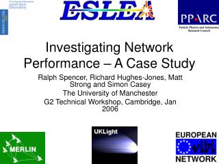
TiNet - A Concept Study for a Titan Geophysical Network. LANGE Caroline, DEMBROVSKIS Andis, GROßE Jens, KOCH Aaron, MAIWALD Volker, QUANTIUS Dominik, ROSTA Roland, WAGENBACH Susanne, ZABEL Paul, VAN ZOEST Tim, SOHL Frank, KNAPMEYER Martin. IPPW-9, 2012, Toulouse, France. Study Overview.

E N D
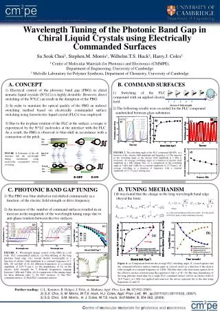
TiNet - A Concept Study for a Titan Geophysical Network LANGE Caroline, DEMBROVSKIS Andis, GROßE Jens, KOCH Aaron, MAIWALD Volker, QUANTIUS Dominik, ROSTA Roland, WAGENBACH Susanne, ZABEL Paul, VAN ZOEST Tim, SOHL Frank, KNAPMEYER Martin IPPW-9, 2012, Toulouse, France
Study Overview • Context: HGF Alliancefor Planetary Evolution and Life • Assess the potential for emergence and evolution of life on a planetary body • Concept Car missions to answer the relevant scientific questions • Go beyond the current NASA and ESA planning (low importance of cost and politics considerations) • Why a geophysical network on Titan? • Big research theme: interior of planetary bodies, and the interaction of interior-surface-atmosphere • Titan due to its concurrent similarity with icy satellites as well as terrestrial planets + its uniqueness with regard to its surface conditions, atmosphere, interior is a key to increase the understanding of this topic • How it was done: • CE-Study atthe DLR Concurrent Engineering Facilityperformed in October 2012 + Postprocessingongoing
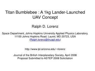
Geosaucer – a mission scenario to learn from… • Titan Geophysics Package aka „Geosaucer“ feasibility study (2008) in the frame of the NASA/ESA TSSM (Titan Saturn System Mission) study • 14 kg instruments and support package accommodated in Montgolfiere heat shield • Instruments: magnetometer, seismometer, radio science • X-band communication with patch antennas • RTG + secondary batteries Frontshield MMRTG* Backshell Montgolfiere Payload Instruments Frontshell support S/S Envelope *Multi-Mission RTG
Scientific Objectives • Measure tidally induced surface displacements + forced librations of outer ice shell • Measure time-variable magnetic field (induced and inducing) to determine location and thickness of internal ocean • Measure the level of seismic activity; determine the structure of outer ice shell and deduce clues on internal ocean • Measure regolith properties • Measure atmospheric composition • Optional: Determine the Titan lake composition
Mission RequirementsandConstraints • Mission goal: • The mission shall establish a network of instrumented landing units on the surface of Titan, which operate simultaneously to measure geophysical parameters of the body • Mission requirements: • The mission shall be set in the 2030+ timeframe. • The mission lifetime shall be as a minimum 1 and maximum 2 Titan days. • The landing sites shall fullfill the following requirements: • 3 stations globally distributed are minimum for seismic measurements • Sites shall: • Be restricted to 2030+ illuminated hemisphere • Cover pole, mid-latitudes (45 deg, leading or trailing hemisphere) and equator (sub- resp. anti-saturnian hemisphere) global dispersion • A local dispersion shall be realized with the sub-landers (3-5 sub-lander)
System Requirements • The total mass of all units shall be < 320 kg (including EDL-subsystem / Thermal Protection) • Functional requirements: • The landing units shall be able to land on solid surface and in liquids • The landing units (Remote units) shall be able to communicate their science and H/K data from any landing site and on-surface attitude to a relay satellite • The landing units shall conduct science experiments autonomously • Performance requirements: • The landing units shall have a lifetime between 1 (T) and 2 (G) Titan days (1 Titan day = 15 Earth days)
Mission Overview – 1/2 Inter-planetary Cruise withSwingbys Arrival at Titan and Orbit insertion Network Deployment, EDL and Operation • A Cassini-size carrier transports the 3 entry probes to Titan • Each probe enters separately and autonomously into the atmosphere, protected by a heat shield • An additional deceleration stage (e.g. parachute) is deployed after heat shield separation. Launch in the 2030s
Mission Overview – 2/2 • During descent the each entry probe, later Hub (main unit) releases 3 Remote Units which are diverted by the wind, e.g. using parachutes/paraglider • Landing on Titan surface (soil or lake) • System start-up and beginning of measurement program • Relay of scientific data to the carrier now functioning as an orbiter in a stable polar orbit
Instruments Small Instruments forgeophysicalmeasurements: (Top left) magnetometerfrom TU Braunschweig, proposedforNetlander; (Top right) Micro-Seismometer; (Bottomleft) Pressuresensorfrom Mars MetNetlander; (Middle) humidity sensor (MetNet); (Bottom right) Tiltmeter (Lorenz)
System Baseline Design - Configuration • Entry Probe: • Innovative sharp edged design toenhancedescentstability. • Predefinedstandardizedpayloadcompartments payload easy excheangeable • EDL • Entry Probe: Passive system, self-stabilizing • Remote Units: Deploymentduringdescent. Parachuteforattitudestabilizationonly • Hub: • Entry Probe reconfigured • Releases Remote Units • Passive attitudecorrection after landing
Baseline Design cont‘d • Power • Hub: GPHS RTG (NASA development), • Pel = 19W max. / Pth = 250 W max. • Remote: Assumption 2/3 physicalsizeof GPHS RTG • Pel = 10W, Pth = 125W • Thermal • Active: Heatof RTG isused. • Heatswitchandradiatortoavoidoverheatingduring cruise • Heatswitchtobeenhanced. • Heatshield: BasotecFoam, Huygens heritage • Communication • UHF link forcommunicationbetween Hub and Remote Units (max. distance: 25km, Pt = 1W) • X-Band foruplinkto Orbiter, 2Mbit/s (Redundance via UHF link) • No DTE
Mass Budget: Total 1280 mm 1100 mm 266 mm 489 mm
Thankyou! The TiNet Study Team
> Lecture > Author • Document > Date Backup Slides
Instrument Suites: Hub • On Hub, but for science during descent: • 1 kg descoped HASI • 0.4 kg descent camera
System Trade 1: Network Architecture vs. Decentralized Architecture Centralized Architecture
Centralized vs Decentralized • Hub/Remote: Central Station (Hub) + 3 simple instrument packages (Remote Units) • Local Network: 3 more „advanced“ instrument packages
Selected Network Architecture • Hub/Remote configuration is the chosen architecture • Lake vs. Soil: different equipment (e.g. some instruments exchanged, eventually modified mechanisms), same configuration
Trade 2: Deployment Scenario cont‘d • Option 1: Hub is carrier for remote units during entry early separation (height 60km) and descent of RU‘s separately • Option 2: deployment after landing • Requirements: from science 1-10 km separation; from communication max. 10 km