Electric Field Measurement Objectives in the Inner Magnetosphere
Professor John R. Wygant of the University of Minnesota outlines key science objectives for the EFW (Electric Field and Waves) instrument. These include measuring electric fields related to particle energization and scattering mechanisms in the inner magnetosphere. Objectives encompass both lower frequency (sub-10 Hz) and higher frequency (up to 200 Hz) measurements, including phenomena such as steady-state convection electric fields and electromagnetic wave interactions. Advanced instrumentation, including spin plane booms and spherical sensors, will be utilized to gather comprehensive data on electric fields and their roles in energetic particle dynamics.

Electric Field Measurement Objectives in the Inner Magnetosphere
E N D
Presentation Transcript
EFW Science Professor John R. Wygant University of Minnesota
EFW Level-1 Science Objectives Science Objectives: Measure electric fields associated with a variety of mechanisms “causing particle energization and scattering” in the inner magnetosphere”. These mechanisms (paraphrased) include: • At lower frequencies (< 10 Hz Survey): • Energization by the large-scale “steady state and storm time convection E-field” • Energization by substorm “transient fronts”propagating in from the tail • “Radial diffusion of energetic particles” mediated by “ULF waves” • Transport and energization by interplanetary “shock generated transient fronts.” • At higher frequencies ( <200 Hz Burst ): • Adiabatic and non-adiabatic energization by “electromagnetic and electrostatic” waves and (“random”) structures in the ELF, VLF frequency ranges (Level 1 calls for electrostatic and electromagnetic field amplitudes, frequency, intensity, propagation direction, spatial distribution and temporal evolution, wave energy, polarization, saturation levels, coherence, wave normal angle, phase velocity, and wave number).
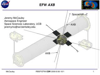
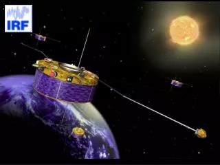
Instrumentation +Z • Four spin plane booms (2 x 40m and 2 x 50m) • Two spin axis stacer booms (2 x 7m) • Spherical sensors and preamplifiers near outboard tip of boom (400kHz response) • Flexible boom cable to power sensor electronics & return signals back to SC • Sensors are actively current biased by instrument command to be within ~ 1 volt of ambient plasma potential. 2 • EFW Science quantities include: • E-fields:(V1-V2, V3-V4, V5-V6) • Interferometric timing: SC-sensor potential (V1s, V2s, V3s, V4s, V5s, V6s) • SC Potential : (V1+V2)/2, (V3+V4)/2 • Survey (<15 Hz) and Burst Data (<200 Hz) 5 4 3 6 Not to Scale 1
Electric Fields in the Active Radiation Belt CRRES measurements of the E-field during a pass through the inner magnetosphere: interplanetary shock induced electric field, large scale MHD waves, and enhancement in convection electric field. MHD waves: an important mechanism for radially diffusing and energizing particles. The shock induced magnetosonic wave created a 5 order of magnitude increase in 13MeV electron fluxes in <100 seconds resulting in a new radiation belt that lasted two years The large scale electric field produced a ~70 kV potential drop between L=2 & L-4 and injected ring current plasma. dDst/dt= - 40 nT/hr
Drivers for Burst Modes Large Amplitude, Small Scale Fluctuations Drive EFW Burst Mode Requirements • Observations of large amplitude turbulent electric fields • Position R=5.2, Mlat 25 deg, MLT=0.5 within RBSP orbit • dE~500 mV/m (Large Amplitude Req.) • Duration of spike 20-200 Hz (Burst E-field Req.) • Polarized perpendicular to B (Burst B-field Req.) • dB~0.5 nT (not shown) • Hodograms for E and B Complicated quasi 3D structure full 3D and 3DB (need 3D E-field and B-field) • Waves electrostatic with phase fronts ~perp to B. (3 D E-field Req.) • Large amplitude thermal plasma variations measured from SC potential variations: Result in order of magnitude changes in index of refraction wave time scales: trapping (Burst SC potential req.) • Observed during nearly conjugate ~400 keV electron microburst interval by low altitude SAMPEX-Candidate Loss Mechanism (Level 1). • Test Particle Simulations suggest waves cause both “prompt” scattering and energization of 50 keV - 3 MeV electrons (Level 1)
EFW Driving Requirements • Spin plane component of E-field at DC-15 Hz (>0.3 mV/m or 10% sensitivity) over a range from 0 to 500 mV/m at R>3.5 Re …(IPLD 38) • Spin axis component of E at DC-15 Hz (>4 mV/m or 20% sensitivity) over a range from 2-500 mV/m at R>3.5Re (IPLD 44) • Spacecraft potential measurements providing estimates of cold plasma densities of 0.1 to ~50 cm-3 at 1-s cadence (dn/n<50%) (IPLD 55) • Programmable high time resolutions burst recordings of large amplitude (Req.: 0.4 -500 mV/m capability: 0-4V/m) E-fields ; B-fields and cold electron density variations 0.1-50 cm-3 with sensitivity of 10% (derived from SC potential) over frequency range from dc to 250 Hz (IPLD 42,47,71, 59) • Burst Interferometric timing of intense (0.1-300mV/m) small scale electric field structures and non-linear waves: timing accuracy of .06 ms for velocities of structures over 0-500 km/s (IPLD 61) • Broad Band Filters (8 freq bins-peak or average) power in wave electric field at 8 samples/s. Burst Triggers/Selection Diagnostic; Solitary Wave Counter: Burst Diagnostic (IPLD 42,47,71,59,61) • Spectra & Cross Spectra of average/peak electric and magnetic fluctuations from 1 Hz to 300 Hz with a cadence of 1/8 seconds over a range 80 dB as a diagnostic of large amplitude wave properties over orbital scales. (IPLD 66,68). • Low noise 3-D E-field waveforms to EMFISIS: 10 Hz to 400 kHz; maximum signal 30 mV/m. For spin plane sensors: range of 100 dB & sensitivities of 3 x 10-14 V2/m2Hz at 1 kHz and 3 x 10-17 V2/m2Hz at 100 kHz. For spin axis sensor pairs: range x 10 less & sensitivity x 100 less (IPLD 245, 246)
Axial Boom Trimming Conceptual Diagram (not to scale) of error contribution due to asymmetric spacecraft charging. Since on-axis sensor (red) are located on different spacecraft equipotentials there is an error field of Err~Vdif/2L where L is boom length. The stacers are motor deployed and during commissioning the length of the booms will be adjusted to minimize this error.