Single Phase Transformers in H. V. Distribution Systems
720 likes | 910 Vues
Single Phase Transformers in H. V. Distribution Systems. Nature of Rural Loads Loads in rural India are predominantly pumpsets used for lift irrigation These loads have low p.f., low load factor Load density is low due to dispersal of loads

Single Phase Transformers in H. V. Distribution Systems
E N D
Presentation Transcript
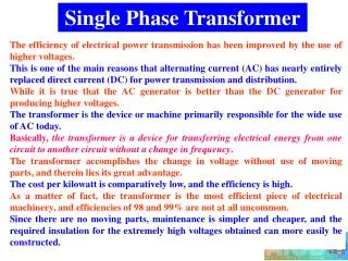
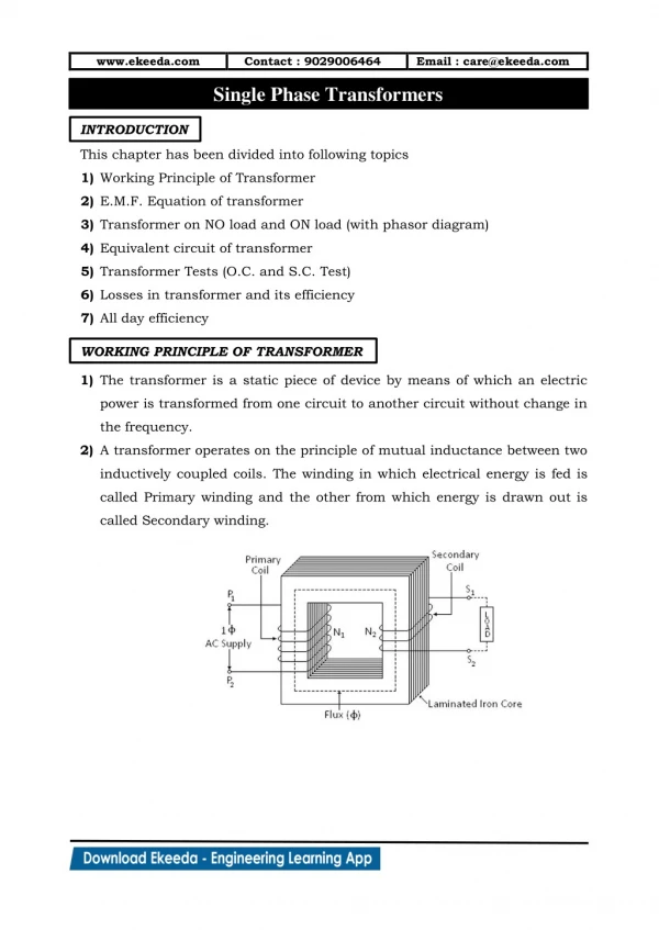
Single Phase Transformers in H. V. Distribution Systems
Nature of Rural Loads • Loads in rural India are predominantly pumpsets used for lift irrigation • These loads have low p.f., low load factor • Load density is low due to dispersal of loads • Existing system is to lay 11 KV lines, employ 3 phase DTRs 11kv / 433 volts and lay long LT lines
Nature of Rural Loads (Contd.) • To fetch a load of one pump set of 5 HP (4 kw) ; two or three L.T. spans are to be laid • On each DTR 63 or 100 KVA 20 to 30 such pump sets are connected. If used for domestic services about 100 consumers can be connected • They run for about 1500 Hrs in an year of 8760 hours.
Disadvantages experienced with LVDS • Poor tail end voltages • High quantum of losses • Frequent jumper cuts and fuse blow outs • Motor burn outs almost twice in each cropping period of 100 days • DTR failures due to frequent faults • Loss of standing crops due to inordinate delays in replacement of failed DTRs
Solution ? H V D S ? • To improve quality of supply and reduce losses HVDS is recommended • 11 KV lines are extended to as nearer to the loads as possible and erect small size single phase transformers 5, 10 or 15 KVA and release supply with NO or least LT line • Aim at “LT less” system starting from “Less LT” • Unavoidable short LT lengths to be covered by insulated wires like ABC (Aerial Bunched Cables)
Technical Superiority of HVDS • For the distribution of same power, the comparison of voltage drop, losses etc., with 100 as base is illustrated below
Technical Superiority of HVDS • Smaller size conductors can be employed • Excellent voltage profile • Reduced losses • No frequent fuse blow outs • Negligible transformer failures • Two or three consumers get effected against 30 if DTR fails (even 100 domestic) • Very easy and quick replacement
HVDS – Single phase - Irrigation • Good quality single phase motors are available • High yield of water as pump set efficiency is high • Single phase motors are ‘capacitor start’ and ‘capacitor run’ • Starters not required • Built in capacitor
Additional advantages of HVDS • Unauthorised hooking of loads is not possible as LT lines are short and insulated • System power factor improves (0.95) causing easy reactive power control • As only two or maximum (3) pump sets are connected on each DTR ; the consumers assume ownership and responsibility • High quality of power supply earns total consumer satisfaction
Questions & Critical issues frequently faced on HVDS • Whether HVDS is for future areas to be electrified or to convert existing LVDS? • Can HVDS & LVDS coexist in the same area? • What is the linkage between load density and type of Distribution System • Economics & payback period • Policy on procurement of single phase transformers
A&B • H.V.D.S. to be implemented straight away where new villages are being electrified in view of its technical superiority • Where 3 phase pump sets are in use HVDS can be implemented by converting existing LT lines for 11 KV • Even three Nos. smaller size single phase transformers can be used for providing three phase LT supply capacity (3Xindividual capacity)
A&B (Contd.) • Single phase transformers 6.3 kv / 233 Volts can be manufactured with single or two bushings • Three single phase transformers can be connected with HVs in star or delta
n A B C A B C N b c b a c a n Star – Star Vs. Delta - Star
(C) Linkage with current density • In Metro areas with high load densities as high as 20 MW per sq km due to rise multistoried complexes enough load can be met with practically no LT • In smaller urban areas, single phase transformers can be employed selectively for single phase as well as three phase
(C) Linkage with current density (Contd.) • Even if one limb fails, single phase loads on that phase can be distributed on the other two and the failed unit can be replaced very quickly as it is easy to transport and erect • In the case of 3 phase large capacity transformers, entire unit is to be replaced and down time is high
(C) Linkage with current density (Contd.) • In rural areas of low load densities HVDS using one or three Nos. single phase transformers can be employed without any hesitation • Rural loads even village habitat portion are too low and mostly single phase • In villages getting electrified afresh; the load densities are bound to be too low
(D) Economics • Cost of three Nos. single phase transformers of capacity ‘K’ is equal to a three phase transformer of capacity (3K) • Cost of employing three single phase transformers is 1.3 times the cost of a 3 phase transformer • There is no difference in no load losses and full load losses between one 3 phase transformer of 3 K and three Nos. single phase transformer of K
(D) Economics (Contd.) • However current for same capacity is too low at 11 KV compared to LT • For 100 KVA current is 5 Amps at 11 KV and 140 Amps at LT • Line losses get reduced in the ratio 52:1402 (25:19600) • Hence highly economical
(E) Usage of three Nos. single phase against one three phase transformer in urban localities • The schemes being implemented in many rural areas are mostly such as “Kutir Jyothi” and “A Lamp for each house” do not need high capacity transformers. • There are single 5, 10, 15 / 16 capacity transformers also which can be used advantageously in these light load areas
(E) Usage of three Nos. single phase against one three phase transformer in urban localities • This has many advantages as follows • Capacities of single phase units can be so selected to avoid laying LT lines as these units are available in ratings from 5 KVA to 15 KVA • Single phase loads can be connected on individual single phase transformers duly dividing them.
(E) Usage of three Nos. single phase against one three phase transformer in urban localities • In respect of extremely few three phase loads with connected loads of 4 kw or above (very rare in rural areas) three single phase transformers of smaller capacities can be employed. • The loads are too small that they cannot contribute to high unbalances.
(E) Usage of three Nos. single phase against one three phase transformer in urban localities • In the event of one phase unit giving trouble, the loads can be distributed on the other two phase units and the defective unit can be taken out easily • Transport, replacement is very easy and can be done much faster. • In fact a rolling stock of 4% can be maintained at each distribution section office for faster replacement
PROS & CONS in Restructuring existing LVDS to HVDS • 99.99% customers avail supply at 415 / 240 Volts thus operational performance of LV network is key to customer services • Losses in Indian Power System are around 20%. LV system is responsible for high loss scenario as LV line losses are 6 times of target limit and 3 times maximum tolerable limit. Switchover to HVDS alone can bring losses to international norms.
PROS & CONS in Restructuring existing LVDS to HVDS • Power loss for transmission of equal load in LVDS (415V) and HVDS (11000V) lines are in ratio 13:1 • Maximum permissible voltdrop between DSS and customer premises is 10%. Hence compliance with IE rule. 56 on voltage drop is difficult and very expensive in LVDS whereas it is simple in HVDS
PROS & CONS in Restructuring existing LVDS to HVDS • The investigation of typical LV feeders in LVDS indicate that 75% of LV feeders have voltdrop above 5% and is the cause of high losses whereas in HVDS losses on LV line are insignificant. • The current for distribution of same power in L.V.D.S. is high and existing conductors get loaded beyond economic loading limits. It can be avoided by switch over to HVDS
PROS & CONS in Restructuring existing LVDS to HVDS • The monitoring of feeders in LVDS is difficult compared to HVDS as number of feeders to be monitored is in ratio of 60:1 • Unauthorised tapping of LV lines is simple and rampant in LVDS whereas it is very difficult in HVDS • ABC cables with tough insulation are indigenously available
PROS & CONS in Restructuring existing LVDS to HVDS • 3 Phase HVDS • The work involved in restructuring distribution work are • Conversion of existing low voltage lines to single phase 2 wire HV lines • Replacement of existing three phase distribution transformers with small capacity single phase transformers • Utilisation of existing three phase motors.
HIGH VOLTAGE DISTRIBUTION SYSTEM IN APSPDCL
Existing LT Distribution of KOTTUR - SS-I 39 Agl Services 3.6 km LT Line
Existing LT Distribution of Murakambattu - SS-II 24 Agl Services 3.0 km LT Line
Existing LT Distribution of Patnam – SS II 9 Agl Services 1 no Poultry Service 1.59 km LT Line
Existing LT Distribution of Bangaru Palem – SS IV 38 Agl Services 3.3 km LT Line
Existing LT Distribution Network • Present LT Distribution system consists of 3 phase distribution transformer with a capacity of 100 KVA in rural areas which feeds supply to all the consumers through 3 phase 4 wire LT network. • DISADVANTAGES OF EXISTING SYSTEM • Lengthy LT Lines. • Voltage drop at the consumer end. • High I2R losses . • Frequent motor burn-outs due to low voltage and consequent expenditure on repairs. • Transformer failures-expenditure towards repairs and inconvenience to the consumers. Continue…
Damage to standing crops, due to delay in replacement of failed distribution transformers. • Fluctuations in voltages due to more number of consumers connected under this transformer (say 25 to 30 consumers). • Nobody owns the transformer since everybody thinks that others will take care of the transformer.
CALCULATION OF LT LINE LOSSES • Electronic meters fixed on the LV Side of the distribution transformers • All Agricultural Services provided with electronic energy meters. • Energy sent out from the transformer measured. • During the same period energy consumed by the Agricultural consumers measured . • Losses worked out. Continue…
As seen from the previous table results the LT line losses are more in LT distribution network. To overcome this,HVD 3Ph system is introduced by A.P.S.P.D.C.L to maintain better voltages and reliability of supply.
Conversion of existing LT 3ph 4w Line into HT Line Same support with HVD System Existing LT 3Phase 4 wire line on support
HVD SYSTEM 3ph 15KVA Dist.Transformer erected under HVDS to cater 2 to 3 services Original 3ph 100KVA Dist.Transformer replaced with 11KV.CTPT set
H.T. and L.T Layout of HVD System.KOTURU-SS-I 39 Agl Services 3.6 km LT Line 2.6 km converted to HT 1.0 km LT Line 11 Nos 15 kVA DTR’s
H.T and L.T layout of HVD System Murakambattu SS I1 24 Agl Services 3.0 km LT Line 2.04 km converted to HT 0.96 km LT Line 10 Nos 15 kVA DTR’s
H.T. and L.T Layout of HVD System.Patnam SS-II 9 Agl Services 1.59 km LT Line 1.59 km converted to HT 8 Nos 15 kVA DTR’s
H.T and L.T layout of HVD System Bangaru Palem SS IV 38 Agl Services 3.3 km LT Line 2.5 km converted to HT 0.8 km LT Line 9 Nos 15 kVA DTR’s
HVD SYSTEM • Existing LT Lines converted into HV Lines by replacing • L T 3-Phase crossarm by 11KV . V crossarm • Replacement of 3 number L T pininsulators with 3 number 11KV pin insulators. • Replacement of 3 number LT shackles with 3 number 11KV strain insulators . • Erection of additional supports where ever clearances are inadequate. • Erection of smaller capacity 3 phase distribution transformer of 15 KVA capacity for every 2 to 3 pumpsets. • Connection of existing pumpsets from the newly erected 15KVA distribution transformers with airbunched cable .
Calculation Of HT Line Losses in HVD System • 11 KV CT PT set erected in place of existing 100 KVA Distribution Transformer • Readings taken simultaneously at CT PT set and at all pump sets. • Losses worked out. Continue…